
Calibration
This MotoHawk™ block enables the declaration of calibration variables. Such variables are exposed to suitable Instrumentation Tools (calibration tools) that will allow run-time modification and observation of the variable.
Block ID
motohawk_calibration
Library
MotoHawk_lib/Calibration & Probing Blocks
Description
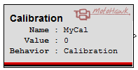
The block behaves in simulation like a Constant block, and accepts any Matlab value that uses a basic Matlab data type as its Default Value, including data-typing casts. Custom data types are not valid and will display an update error.
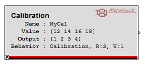
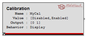
Some labels on the block are only displayed when certain modes are selected in the mask parameters. The 'Output' label shows value(s) that will be exported to the block's output port. The 'Output' label is only shown when its value is different from the engineering 'Value'. The engineering 'Value' will be different if gain, offset or exponent are not 1, 0 and 1 respectively. See the Engineering Values versus Native Values help topic for further information.
When the Read or Write access levels are not 1, they are displayed alongside the behavior.
If the value displayed on the block has an asterisk (*) next to it, this indicates that the value is being overridden by a workspace calibration struct
variable, called
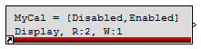
Some items are hidden or re-arranged when the block is made small in order to continue to display essential information. Increase the block size to see more detail.
Block Parameters
Definition Tab
The following parameters define the Calibration data storage
| Parameter Field | Values | Comments/Description |
|---|---|---|
| Name Source | Select source for Name parameter | |
| Use Parameter | Define Calibration name in Name field | |
| Use Output Wire Name | Define Calibration name from the output wire name | |
| Name | Alpha-numeric text, single-quote enclosed | Visible if "Use Parameter" is selected in "Name Source." Name exposed to Instrumentation. Should be unique and C-legal (no special characters, such as spaces, dashes or commas (underscore allowed). |
| Default Value | The default value of the calibration. This block will behave as a constant block that will output the Default Value. Specify the native value (not the engineering value). See the Engineering Values versus Native Values for further information. NOTE: value can be overriden depending on the state of the 'Use uploaded calibration values' checkbox. | |
| Behavior (storage class) | Define type of block behavior | |
| Calibration | Flash calibration variable created | |
| Display | RAM calibration variable created. | |
| Calibration NV | NonVolatile calibration variable created. | |
| Display NV | NonVolatile variable created that is not considered to be part of the calibration. | |
| Calibration Fixed NV |
Behavior is similar to Calibration NV and Display NV, but data is stored as Fixed NonVolatile. Fixed NonVolatile data allows for greater flexibility by permitting the addition of new data items whilst retaining existing data during an application upgrade. | |
| Display Fixed NV | ||
| Use uploaded calibration values | Checkbox enable | Enable/disable to use or ignore uploaded calibration values. This field is only shown for some Behaviour types. |
| Output Data Type | Set Data Type for Output | |
| Inherit from Default Value | Takes Data Type from default value entered | |
| Inherit via back propagation | Set Data Type via back propagation from the attached Simulink signals | |
| double, single, int8, etc. | Select Data Type from types listed | |
| Specify Memory Region | Check box (enable) | Selects that the data will be placed in region specified by Memory Region Name. This option is only available if the target and selected storage class support memory regions. The default memory region is used when this option is not available or unchecked. |
| Memory Region Name | Alpha-numeric text, single-quote enclosed | Name of the Memory Region in which to place the data. This option is only available when Specify Memory Region is checked. |
Instrumentation Access Tab
The following parameters control the access of the parameter to instrumentation
| Parameter Field | Values | Comments/Description |
|---|---|---|
| Read Access Level | 0-8 | Sets security level 1 lowest, 8 highest, for user access to read value. A setting of zero indicates unsecured access is allowed. |
| Write Access Level | 0-8 | Sets security level 1 lowest, 8 highest, for user access to write value. A setting of zero indicates unsecured access is allowed. |
| View Value as | Sets "Default Value"data type | Number | Numeric value |
| Enumeration | Enables enumeration - maps to the indicated term in the Enumeration text-entry field | |
| Text | Text string | |
| Enumeration (Cell String, or Struct) | Alpha-numeric text, single-quote enclosed |
Field visible when Enumeration is selected under "View Value as." Enter
term of defined entity to be mapped. Cell String: A cell array of strings such as {'Off', 'On'} may be used to define the names of enumerated values. In this case, the values start with 0 and increment by one. This is especially useful for defining names for boolean flags like 'On' and 'Off'. Struct: A Matlab struct array containing a 'name' field, and optionally a 'value' field may be used to define the names and explicitly define the values of an enumerated type. For example: struct('name', {'Off', 'On'}, 'value', {0,1}). If the 'value' field is missing, then the values start with 0 and increment by one, just like with the Cell String format. Note that only integer or boolean values may be used with enumerations. Floating point types such as double and single are not allowed. |
| Show Vectors As | Wide Row/Tall Column | Format vector output as row or column. The field only applicable when the Default Value in the definition page is a vector or matrix |
| Row Header Enumeration | Alpha-numeric text, {} bracket enclosed |
Field only applicable when the Default Value in the Definition Tab is a vector or matrix.
Cell String: A cell array of strings such as {'Off', 'On'} may be used to define the names of enumerated values. In this case, the values start with 0 and increment by one. This is especially useful for defining names for boolean flags like 'On' and 'Off'. Struct: A Matlab struct array containing a 'name' field, and optionally a 'value' field may be used to define the names and explicitly define the values of an enumerated type. For example: struct('name', {'Off', 'On'}, 'value', {0,1}). If the 'value' field is missing, then the values start with 0 and increment by one, just like with the Cell String format. |
| Column Header Enumeration | Alpha-numeric text, {} bracket enclosed |
Field only applicable when the Default Value in the Definition Tab is a vector or matrix.
Cell String: A cell array of strings such as {'Off', 'On'} may be used to define the names of enumerated values. In this case, the values start with 0 and increment by one. This is especially useful for defining names for boolean flags like 'On' and 'Off'. Struct: A Matlab struct array containing a 'name' field, and optionally a 'value' field may be used to define the names and explicitly define the values of an enumerated type. For example: struct('name', {'Off', 'On'}, 'value', {0,1}). If the 'value' field is missing, then the values start with 0 and increment by one, just like with the Cell String format. |
| Instrumentation Group | Alpha-numeric text, single-quote enclosed | Defines the desired Folder name and hierarchy to be used by suitable Instrumentation Tools. Use "|" character between folder names to delineate subfolder structure. |
Instrumentation Units Tab
The following parameters control the instrumentation data conversion and display format
| Parameter Field | Values | Comments/Description |
|---|---|---|
| Help Text | Alpha-numeric text, single-quote enclosed | Enter help text to describe parameter purpose, available to tools for display |
| Units | Alpha-numeric text, single-quote enclosed | The engineering units associated with this variable. |
| Minimum Value | Numeric Value |
Sets the lower end of the allowable range for the calibration. The specified value is in engineering units
(see Engineering Values versus Native Values). Typically this value is used by instrumentation to prevent a user from entering an out of range value when calibrating. |
| Maximum Value | Numeric Value |
Sets the higher end of the allowable range for the calibration. The specified value is in engineering units
(see Engineering Values versus Native Values). Typically this value is used by instrumentation to prevent a user from entering an out of range value when calibrating. |
| Precision | Alpha-numeric text, single-quote enclosed | Sets the desired precision of the variable for use by suitable Instrumentation tools. For instance, if the variable has a value of 98.76543 and the precision is ‘1.3’, the value displayed would be 98.765. |
| Gain* | Numeric Value | Multiplier component of the conversion equation that converts a native value into an engineering units value (see Engineering Values versus Native Values). |
| Offset* | Numeric Value | Offset component of the conversion equation that converts a native value into an engineering units value (see Engineering Values versus Native Values). |
| Exponent* | Numeric Value | Exponent component of the conversion equation that converts a native value into an engineering units value (see Engineering Values versus Native Values). |
*NOTE: Engineering Value = ((Native Value * Gain)^Exponent) + Offset
See the Engineering Values versus Native Values help topic for further information.