
Reaction Module
This MotoHawk™ block defines the global configurations of Freescale Semiconductor's Reaction Module (REACM) that exists on some microcontrollers (like the MPC564x).
Block ID
Reaction Module
Library
MotoHawk_lib/ModuleConfiguration
Description
Overview
This MotoHawk™ block defines the global configurations of NXP's Reaction Module (REACM) that exists on some microcontrollers (like the MPC564x). This silicon module simplifies the control of actuators through the use of software that is tightly coupled to the microcontroller's hardware. Refer to NXP's documentation for further information on this module.
The Reaction Module has a direct connection with the on-chip ADC that allows highspeed sampling of loads currents that can then be used in the feedback loop for current modulation by PWM. The ADC is sampled at high frequency and the results supplied to the Reaction Module for use. Thus the load current is presented the Reaction Module as a digitized representation. MotoHawk™ selects the sampling rate based upon worst case ADC loading so that actuator behavior remain consistent regardless of the number of reaction channels that may be in use by the system.
The Reaction Module Status block provides access to the latest observed status of the Reaction Module. This can be used to detect whether there has been software problem with the creation of the block. It can also detect if there is a setup problem that is causing the ADC to suffer from overrun events.
Reaction Channel Behaviors
The Reaction Module is constructed from Reaction Channels that perform the load current modulation. The style of modulation is abstracted by MotoHawk™ reaction channel behaviors. These behaviors take into account the external circuitry connections and abstract the control aspects of the behavior to the developer for configuration. Supported behaviors include:
Other related blocks
- Reaction Module Status block
- React Off Time block
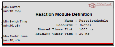
Signals
Max Current (mA)
Max Current defines the maximum load current that a reaction module channel would expect to see. A short circuit condition is detected if this threshold is exceeded. This value applies to all reaction channels. The largest resultant ADC threshold is used when a reaction module has the choice between different load current to ADC transforms. The Peak/Hold Controller block provides further detail on how this attribute relates to faults and thus how it should be tuned.
Min Switch Time (us)
Min Switch Time specifies the start of the window where switching events should be observed. A short circuit condition might be implied if the channel does not remain asserted for this minimum time. This value applies to all reaction channels (limitation of the silicon) and thus must be tuned so as to take different load characteristics into account. It is a signal so that it can be altered at runtime to account for things like variation with battery voltage. Set to zero to disable (though this disables all reaction module diagnostics on all channels). The Peak/Hold Controller block provides further detail on how this attribute relates to faults and thus how it should be tuned.
Max Switch Time (us)
Max Switch Time specifies the end of the window where switching events should be observed. An open circuit condition might be implied if the channel remains asserted for longer than this time. This value applies to all reaction channels (limitation of the silicon) and thus must be tuned so as to take different load characteristics into account. It is a signal so that it can be altered at runtime to account for things like variation with battery voltage. Set to zero to disable. The Peak/Hold Controller block provides further detail on how this attribute relates to faults and thus how it should be tuned.
Block Parameters
| Parameter Field | Values | Comments/Description |
|---|---|---|
| Name | Alpha-numeric text, single-quote enclosed | This name will be used by associated blocks like the Reaction Module Status block to reference this Reaction Module definition. No special characters, such as spaces, dashes and commas (underscore allowed) |
| Internal Resource | Drop-down list | Select output resource for this block (target module dependent). |
| Shared Timer Tick | Positive Integer | The Reaction Module has a number of Timers that Reaction Channels can use to time when to switch from one Modulation style to another. They have a finite length. The MPC564x core supports 12bit timers. The timers support prescaler functionality that allows the developer to define the compromise between granularity and timer range. The supplied value is used by MotoHawk™ to assist the setup of this prescaler. |
| Hold Off Timer Tick | Positive Integer | The Reaction Module supports "Hold Off" timers that Reaction Channels can use to time how long a channel should remain off when when an ADC threshold has been reached. They have a finite length. The MPC564x core supports 8bit timers. The timers support prescaler functionality that allows the developer to define the compromise between granularity and timer range. The supplied value is used by MotoHawk™ to assist the setup of this prescaler. |