
Variable Reluctance (VR) Signal Behavior
Many modules have input circuits that are designed to interface with variable reluctance sensors (VRS). Such sensors are used to detect teeth of a rotating wheel and are thus commonly used in encoder systems like the MotoHawk Flexible Encoder and Encoder behaviors. The signal from such sensors is sinusoidal and requires hardware circuitry to transform that signal into a digital signal that a microcontroller can interpret. There are some considerations that the application designer should consider when working with VR signals.
Expected Setup Polarity
A VR signal has a distinctive zero-crossing aspect of the signal that results as the tooth is detected because of the change in the flux profile about the tooth. The zero point accurately describes the tooth location and is practically invariant to speed of rotation. VR signal processing associates one edge of the digital pulse train that describes the VR signal with this zero-crossing point. It is this edge that is considered the synchronous edge and would be used by the system to represent when a tooth was observed. Crank angle position and engine speed are determined from the synchronous edge. The other edge is typically associated with the observance of a setup voltage. This setup voltage is often adaptive, trending upward as the average signal amplitude is increasing so as to provide improved noise immunity.

The VR circuit of MotoHawk modules associate the zero-crossing event with the observance of a zero voltage during the signal transition from a positive voltage to a negative voltage. MotoHawk modules therefore expect that sensor to be connected so that a positive voltage is observed first.
The Flexible Encoder Source definition block and Legacy Encoder definition block provide a means for the behavior to select what edge is the synchronous edge. This setting is generally ignored when a VR interface is in use because MotoHawk is assuming a specific interface. The flexible encoder allows this behavior to be overridden by the application. There are implications that should be considered before doing this.
Inverted Setup Polarity
The module will still function if the VR signal is inverted, though the function may not be optimal. Inversion can be introduced by connecting the sensor incorrectly. Sensor connection needs to be considered when moving from a target with raised teeth to one with holes.

Impact of Inversion on an Encoder Using Default Handling
An incorrectly connected VR signal that results in an inverted signal being supplied to an unaware encoder system can manifest itself as
unexpected behavior including:
- Variation in tooth location
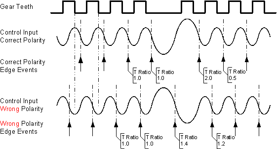
The encoder system considers the zero-crossing point of the signal to describe the synchronous edge, but this edge's location will vary (see the green shading of the figure). There is no definitive zero-crossing point. The point of inflection (see figure) introduces variability in where the circuit detects the zero crossing voltage and will be more pronounced at lower speeds. At higher speeds the VR signal is almost sinusoidal and there is no point of inflection, which often hides the low speed performance issues. - Variation in key detection (missing tooth detection)
Missing tooth detection can be impacted because the behavior of the signal around the missing teeth leads to unexpected ratio values.
Impact of Inversion on an Encoder that can select the synchronous edge
Sometimes it is not practical or possible to alter the connections so as to achieve a VR signal with the polarity that MotoHawk expects. The problems detailed in the section above can be worked around if MotoHawk can be appropriately configured. Flexible Encoder allows the behavior where MotoHawk assumes the signal polarity to be overridden. This is done by clearing the Hardware Sets VR Edge Sync checkbox.
Having software work around the problem of utilizing a VR signal with the incorrect polarity means that the operation may not be optimal. Some areas
of operation to consider are discussed below:
- Variation in tooth location because of the adaptive setup
Many VR circuits utilize an adaptive setup threshold, which means the absolute voltage that must be observed before an output edge is generated will vary with engine speed (see the pink shading of the figure). This variation will introduce an error in the tooth location that is speed dependent. The error may be minimal because the rate of change of the zero-crossing signal will be high. Variations will also likely be of a static nature, which tends to be an error that is inherently compensated for with calibration. - Variation in tooth location because of circuit tolerance
The tolerance of the setup voltage is not typically as tightly controlled as the zero-crossing voltage. This may manifest as position error that is exposed because of variations in the environment such as temperature. The error may be minimal because the rate of change of the zero-crossing signal will be high. - Install to install variation
The setup voltage can vary more widely between modules because this value is not typically tightly controlled. This could influence systems where a single calibration is applied to multiple engine installations.