
MotoHawk ProSAK Filter Coefficients
Block ID
Prosak Filter Coefficients
Library
motohawk_prosak_lib
Description
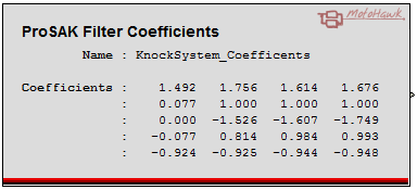
The ProSAK Filter Coefficients block defines a calibration set of IIR filter coefficients. Typically the output of this block will be used as the input of a ProSAK Filter Coefficients Set Block.
Block Parameters
| Parameter Field | Values | Comments/Description |
|---|---|---|
| Name | Alpha-numeric text, single-quote enclosed | Name as displayed in block, Instrumentation, for block. No special characters, such as spaces, dashes, commas (underscore allowed) |
| Filter Coefficients (-4,4)x20 | 1 x 20 vector. | A vector of 20 bi-quad coefficients in the range of (-4,4). See Table 1. for coefficient order. |
| Read Access Level | 1-4 | Sets security level 1 lowest, 4 highest, for user access to read value. |
| Write Access Level | 1-4 | Sets security level 1 lowest, 4 highest, for user access to write value. |
| Calibration Group String | Alpha-numeric text, single-quote enclosed | Determines Folder name and hierarchy as displayed in the calibration tool. Use "|" character between folder names to delineate sub-folder structure. |
Programming the IIR Filter
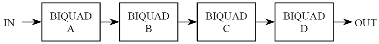
The digital programmable filter is a digital 8th order IIR filter. The programmable filter is implemented as a cascade of four digital bi-quads as shown in Figure 1 below. Each bi-quad can handle up to two poles and two zeros so that the entire filter can handle filter designs up to eight poles and eight zeros.
|
The filters have the form:
| h(z) = | b0A+b1Az-1+b2Az-2 | X | b0B+b1Bz-1+b2Bz-2 | X | b0C+b1Cz-1+b2Cz-2 | X | b0D+b1Dz-1+b2Dz-2 |
| 1+a1Az-1+a2Az-2 | 1+a1Bz-1+a2Bz-2 | 1+a1Cz-1+a2Cz-2 | 1+a1Dz-1+a2Dz-2 |
b0A represents the b0 numerator coefficient for biquad A
a2D represents the a2 denominator coefficient for biquad D
Twenty total coefficients (five per biquad) are set using the Filter Coefficients Set Block. Each coefficient is a number that ranges between -4.0 and +4.0. The block converts them into a fixed point form that is suitable for use with the ProSAK.
To program the filter, first design a digital filter that has a maximum of 8 poles and 8 zeros. Next, allocate the poles and zeros to the four biquads, A-D. From these pairs of poles and zeros, determine the correct values for the coefficients: b0, b1, and b2 for the pairs of zeros, and a1 and a2 for the pairs of poles. (Note that a0 is always 1.0 for this filter.)
Next, scale the numerator constants, b0, b1, and b2, for each biquad to distribute the gain properly. For the first biquad, biquad A, the peak gain should be set to 1.9. For each of the remaining biquads, the peak gain should be set to 1.0. Setting the biquad gains too high will cause overflow within the filter which will result in failure of the knock system. An overflow within the filter will set the IIR Overflow bits in the KNKSTAT0 register. The IIR Overflow bits are also output the calibration port when the calibration port is enabled and setup to output the IIR filter result. Setting the biquad gains too low will increase the rounding error introduced by the digital system.
Coefficient Vector Map
| Vector Index | Coefficient |
|---|---|
| 0 | a1A |
| 1 | a1B |
| 2 | a1C |
| 3 | a1D |
| 4 | b0A |
| 5 | b0B |
| 6 | b0C |
| 7 | b0D |
| 8 | b1A |
| 9 | b1B |
| 10 | b1C |
| 11 | b1D |
| 12 | b2A |
| 13 | b2B |
| 14 | b2C |
| 15 | b2D |
| 16 | a2A |
| 17 | a2B |
| 18 | a2C |
| 19 | a2D |