
MotoHawk ProSAK System Definition
The ProSAK System definition sets up a ProSAK knock input. It is required if any other ProSAK blocks are to be used.
Block ID
MotoHawk_prosak_def
Library
motohawk_prosak_lib
Description
Block Parameters
| Parameter Field | Values | Comments/Description |
|---|---|---|
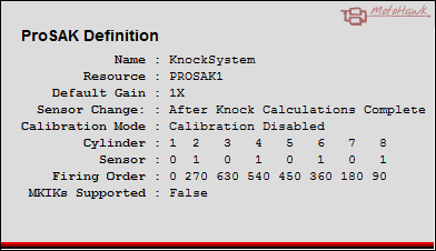
| Name | Alpha-numeric text, single-quote enclosed | Name of the ProSAK System that other blocks will use to reference this definition. |
| Resource | Drop down list | The list of resources that are capable of supporting a ProSAK System. |
| Active Cylinder Count * | Numeric 1 to 12. | The number of cylinders to support, may be less than the maximum number of cylinders. |
| Firing Order * | A 1 x Max Cylinder Count vector of angles representing firing order, or a vector of cylinder numbers if vector timings are not supported. | Firing Order is a vector of angles that represent the firing order, if the module does not support vector timings this will instead be a vector of cylinder numbers representing the firing order. The size of this vector will set the maximum number of cylinders allowed. |
| Sensor Selection * | Vector of 0's and 1's. | Sensor Selection is a vector of 1's and 0's indicating the pin to use for each cylinder. Must be the same size as the firing order vector. |
| Default Sensor Gain * | Drop Down (1X or 2X) | Default Gain is the gain (1X or 2X) that the device will apply to the inputed sensor signal. |
| Sensor Select Change * |
After Knock Calculations Complete After Reference Calculation Complete |
Sensor Select change is the setting that defines when the sensor will be changed. |
| Calibration Mode * |
Disabled, Backend, IIR + Comb Calibration, IIR + Coefficient Calibration |
Controls the setup of the calibration port. See PROSAK CALSETUP description in the PROSAK manual, for more information. |
| Notification Mode * |
Disabled, Knock Indicator, Knock Valid, Knock Indicator or Knock Valid, Reference Valid, Knock Indicator or Reference Valid, Knock Valid and Reference Valid |
Notification Mode defines the method to use to for notification. See PROSAK KOSEL description in the PROSAK manual, for more information. |
| Scaling * |
16.0 - bbbbbbbbbbbbbbbb. 15.1 - bbbbbbbbbbbbbbb.b 14.2 - bbbbbbbbbbbbbb.bb 13.3 - bbbbbbbbbbbbb.bbb 12.4 - bbbbbbbbbbbb.bbbb 11.5 - bbbbbbbbbbb.bbbbb 10.6 - bbbbbbbbbb.bbbbbb 9.7 - bbbbbbbbbb.bbbbbb 8.8 - bbbbbbbbb.bbbbbbb 7.9 - bbbbbbbb.bbbbbbbb 6.10 - bbbbbb.bbbbbbbbbb 5.11 - bbbbb.bbbbbbbbbbb 4.12 - bbbb.bbbbbbbbbbbb 3.13 - bbb.bbbbbbbbbbbbb 2.14 - bb.bbbbbbbbbbbbbb 1.15 - b.bbbbbbbbbbbbbbb 0.16 - .bbbbbbbbbbbbbbbb |
Scaling defines where the decimal resides for the KNOK0-11, KNKR and KNKI registers. |
| Include M-KIKs Support | Checkbox | If Checked, the MKIKs calibration support will be included, and will consume additional resources. |
| Enable M-KIKs Support * | Checkbox | If checked the MKIKS support signals will be enabled by default. |
| Read Access Level | 1-4 | Sets security level 1 lowest, 4 highest, for user access to read value. |
| Write Access Level | 1-4 | Sets security level 1 lowest, 4 highest, for user access to write value. |
| Calibration Group String | Alpha-numeric text, single-quote enclosed | Determines Folder name and hierarchy as displayed in the calibration tool. Use "|" character between folder names to delineate sub-folder structure. |