 |
|
|
Many modules have input circuits that are designed to interface with variable reluctance sensors (VRS). Such sensors are used to detect teeth of a rotating wheel and are thus commonly used in encoder systems like the MotoHawk Flexible Encoder and Encoder behaviors. The signal from such sensors is sinusoidal and requires hardware circuitry to transform that signal into a digital signal that a microcontroller can interpret. There are some considerations that the application designer should consider when working with VR signals.
A VR signal has a distinctive zero-crossing aspect of the signal that results as the tooth is detected because of the change in the flux profile about the tooth. The zero point accurately describes the tooth location and is practically invariant to speed of rotation. VR signal processing associates one edge of the digital pulse train that describes the VR signal with this zero-crossing point. It is this edge that is considered the synchronous edge and would be used by the system to represent when a tooth was observed. Crank angle position and engine speed are determined from the synchronous edge. The other edge is typically associated with the observance of a setup voltage. This setup voltage is often adaptive, trending upward as the average signal amplitude is increasing so as to provide improved noise immunity.
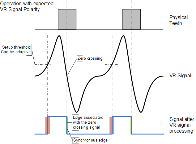
The VR circuit of MotoHawk modules associate the zero-crossing event with the observance of a zero voltage during the signal transition from a positive voltage to a negative voltage. MotoHawk modules therefore expect that sensor to be connected so that a positive voltage is observed first.
The Flexible Encoder Source definition block and Legacy Encoder definition block provide a means for the behavior to select what edge is the synchronous edge. This setting is generally ignored when a VR interface is in use because MotoHawk is assuming a specific interface. The flexible encoder allows this behavior to be overridden by the application. There are implications that should be considered before doing this.
The module will still function if the VR signal is inverted, though the function may not be optimal. Inversion can be introduced by connecting the sensor incorrectly. Sensor connection needs to be considered when moving from a target with raised teeth to one with holes.
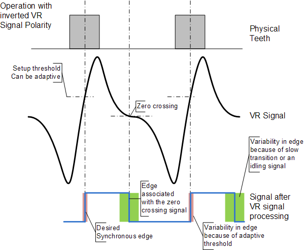
An incorrectly connected VR signal that results in an inverted signal being supplied to an unaware encoder system can manifest itself as
unexpected behavior including:
Sometimes it is not practical or possible to alter the connections so as to achieve a VR signal with the polarity that MotoHawk expects. The problems detailed in the section above can be worked around if MotoHawk can be appropriately configured. Flexible Encoder allows the behavior where MotoHawk assumes the signal polarity to be overridden. This is done by clearing the Hardware Sets VR Edge Sync checkbox.
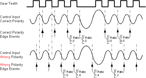
Having software work around the problem of utilizing a VR signal with the incorrect polarity means that the operation may not be optimal. Some areas
of operation to consider are discussed below:
| Copyright 2014 Woodward Corporation. All Rights Reserved. | Visit Us: mcs.woodward.com |