 |
|
|
An Absolute Source refers to an encoder source that may be used by the encoder system to provide crank synchronous behaviors (like injection) with a high resolution tooth interpolated absolute crank angle position. A Companion Source is also an encoder source except that it is not used to provide absolute crank angle position. Companion sources are used to help synchronize an absolute source (e.g. tooth synchronizer pattern) and/or provide halfcycle information (e.g. camshaft pattern). There is often fewer resources required by a companion only source compared to the resources needed by an Absolute Source and so more module resources can usually support such inputs.
The motohawk_flexencoder_project script can be used to create a sample flexible encoder application. Different types of system can be created with this script.
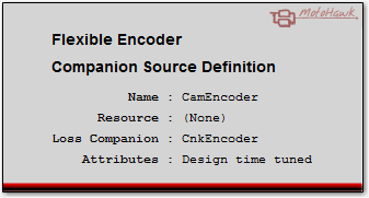
Companion Source Definition
motohawk_flexenc_lib
| Parameter Field | Values | Comments/Description | Calibration Name |
|---|---|---|---|
| Name | Alpha-numeric text, quote enclosed |
Name of the encoder source that other blocks will use to reference this definition. This name is also used in the construction of the names of attributes that support calibration. |
|
| Resource | Drop down list | The list of resources that are capable of supporting this behavior. There is often more resources with the capability of supporting a companion source when compared to an Absolute Source. | |
| Pattern Selector | Alpha-numeric text, quote enclosed | This text associates this companion encoder source definition with an encoder pattern definition. The name used by the Flexible Encoder Pattern Definition that is to be referenced should be used here. | {Name}_PatternSelector |
| Define Enumeration Order | Check box |
Check to allow the application to control the order that Flexible Encoder sources are enumerated by the system. This can be useful
when using calibration tools that deal directly with the value rather than the enumeration. Controlling the enumeration order for
all sources in the model will ensure that the same value is always associated to the same source. Source's may need to support
enumeration when options like flexible connectivity are utilized. The This Source ID attribute of the Get Source Info block reflects how the system enumerated the source. |
|
| Order | numeric | This value controls how Flexible Encoder sources are enumerated. A low value will enumerate before another source that has a higher value. Those sources that have not checked the Define Enumeration Order will be considered before those sources that do have Define Enumeration Order checked. |
| Parameter Field | Values | Comments/Description | Calibration Name |
|---|---|---|---|
| Create Source | Check Box (True/False) |
Check this box to have the application create this source. Defining the source without creating it (not checked) reserves the software resources necessary to support this encoder source, but won't physically create that source. This box is normally checked and needs to be checked if the source does not support calibration. Calibration control of the creation allows a source to be disabled so that it can't influence the system, which is often a desired outcome when using flexible connectivity. | {Name}_CreateSource |
| Num Revs Per Cycle | 1 or 2 | Defines how many times this encoder source will revolve in an engine cycle. A crankshaft encoder source used in a 4-stroke application will revolve twice per cycle where as a camshaft source would only revolve once. | {Name}_NumRevsPerCycle |
| Is Rising Edge Sync | Falling Edge(False) Rising Edge(True) by Drop Down |
Defines the signal edge that represents absolute crank angle position. This should align to the edge that defines the LogicalDeg entry of the associated encoder pattern. This attribute is only considered when digital sensing technologies are in use. A resource that has a Variable Reluctance input stage will, by default, ignore this setting as the edge to use is defined by the hardware circuit rather than by the pattern itself. Uncheck the Hardware Sets VR Edge Sync attribute to override this default behavior and allow the Is Rising Edge Sync setting to be used with an input that has a VR interface. | {Name}_IsRisingEdgeSync |
| Hardware Sets VR Edge Sync | Check box | This setting only applies when a Variable Reluctance interface is in use. MotoHawk determines which edge to use automatically when this attribute is checked (which is the default). MotoHawk will only use the Is Rising Edge Sync setting for synchronous edge determination when this attribute is not checked. VR Signals are discussed further here. | {Name}_HardwareSetsVREdgeSync |
| Good Keys to Clear Fault | Numeric, 1 to 255 | Internal behavior is sometimes dictated by whether the encoder system believes that the source is in error. For example an encoder that suffers from a loss of signal fault may require a number of good key matches to occur before the source is said to now be good. This is more often used to ratify whether a companion source is considered valid, like whether a camshaft signal can be trusted to provide halfcycle information. The larger the value the longer it will take for the encoder to be considered valid again. | {Name}_GoodKeysToClrFault |
| Key Aligns (with companion source) | Check box | When checked (True) this attribute signifies that a key event of this source aligns with teeth of this source's Loss Companion. This is most notably seen on single tooth halfcycle and synchronizing companion sources. See here for a detailed explanation on when to check or uncheck this attribute. | {Name}_KeyAligns |
| Phase Reporting | Drop Down | Indicates the phase reporting capability of this source. Installing phase reporting consumes resources, even if it is disabled. Selecting Not Created will prevent the source from consuming these resources. Typically the primary absolute source (e.g. crank encoder) will set phase reporting to Not Created since there is no value in having the primary source reporting phase that is measured relative to itself. Selecting Disabled will install the feature (consuming resources), but it won't consume execution bandwidth. There is no value in selecting Disabled if the source does not support attribute calibration. Enabled - Limited will only generate a phase report trigger on tooth #0. This consumes less execution bandwidth than does the Enabled - Full selection. Limited operation is useful if the phase of a source relative to the absolute source is to be determined, but where the phase relationship is constant. Use Enabled - Full when a variable phase relationship exists, such as when variable cam timing is available. Enabled - Full generates a phase report trigger on every tooth of the source and thus consumes the most execution bandwidth. |
{Name}_PhaseReportingCondition This calibration attribute is available provided the mask attribute was not set to Not Created. |
| Override System Zero Speed Timeout | Checkbox | Check to allow this source to specify its own Zero Speed Timeout instead of using the system level Zero Speed Timeout. | |
| Zero Speed Timeout (ms) | Integer zero or greater |
Defines the time without any activity on this source before this encoder source considers that it has observed a zero speed condition. So a value of
1000 implies that if this encoder source does not observe any teeth in 1000ms then it will be considered to have observed a zero speed condition. The
Encoder State will report ZERO_SPEED if this source is the active source. The system level Zero Speed Timeout will be used instead of this value unless Override System Zero Speed Timeout is checked or if a timeout of zero is specified. |
{Name}_ZeroSpeedTimeout This calibration attribute is available when Override System Zero Speed Timeout is checked. |
| Parameter Field | Values | Comments/Description | Calibration Name |
|---|---|---|---|
| Name of Loss Companion | Alpha-numeric text, quote enclosed | Name of the encoder source that this source shall use to detect loss. The Loss Companion must be the name of another Absolute source block. The Loss Companion of a Companion Source cannot be the name of another Companion Source. A companion source will always have a loss companion because a companion source will never exist in a design without at least one absolute source. If this source(a) is to operate as either a halfcycle and/or synchronization companion for another source(b) then this source(a) needs to use source(b) as its loss companion. | |
| Teeth Before Loss | Numeric greater than one | The number of teeth that need to be observed by the referenced encoder source (Name of Loss Companion) without a tooth being observed on this encoder source before this encoder source is considered to have suffered a loss failure. Consider a 4-stroke 60M2 crank used with a tooth cam. The crank would only need to observe two teeth on the cam before it could be considered to have suffered loss (can't be one because that would indicate a fault each time a tooth was observed). The cam could conceivably observe all 58 teeth (has two missing so it is not 60) twice (because it rotates twice as fast as the cam) and still not have observed the cam. But observe 1 more and that could indicate loss. In other words the cam's Teeth Before Loss should be at least 117 for this case. | {Name}_LossCompanion_TeethBeforeLoss |
| Detect Phase (error using loss companion) | Check box |
When checked (True) this source should attempt to detect a phase error using the source that is being used to detect the source
loss condition as its reference. There is no value in validating two sources. Therefore, if this source
is configured to detect a phase error, then the source that is being referenced in order to perform that detection shouldn't also attempt
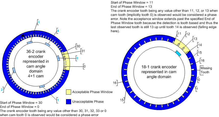
to detect a phase error. A source is said to have suffered a phase error if its zero tooth (as defined by the Pattern Definition Physical Teeth entry of this source's referenced pattern) falls outside the window defined by Phase Start of Window and Phase End of Window. Some example figures illustrate some window setups. |
{Name}_LossCompanion_PhaseDetect |
| Phase Start of Window (Tooth) | Integer | Defines the start tooth for legal phase. | {Name}_LossCompanion_Phase_StartOfWindow |
| Phase End of Window (Tooth) | Integer | Defines the end tooth for legal phase. | {Name}_LossCompanion_Phase_EndOfWindow |
| Parameter Field | Values | Comments/Description | Calibration Name |
|---|---|---|---|
| Allow parameters marked * to be calibrated | Check box | In general parameters with a value in the Calibration Name column of this table will support calibration when this check box is checked. | |
| Read Access Level | 0-8 | Sets security level 1 lowest, 8 highest, for user access to read value. A setting of zero indicates unsecured access is allowed. | |
| Write Access Level | 0-8 | Sets security level 1 lowest, 8 highest, for user access to write value. A setting of zero indicates unsecured access is allowed. | |
| Instrumentation Group | Alpha-numeric text, single-quote enclosed |
Determines folder name and hierarchy that is applied to calibration parameters defined by this table. Use "|" character between folder names to delineate subgroup structure. |
The Key Event Aligns with Companion Source check box is used to signal that the key event of this source occurs in the vicinity of a critical edge of this source's Loss Companion. This is most commonly used by a single tooth cam or synchronizing source whose single tooth, which equates to its key, that occurs in the vicinity of a critical crank tooth. When the key event occurs near a tooth there is a risk that system variations will see the key event that is issued by the source being associated with different teeth on the crank. This can lead to unexpected operation.
Consider a 36 tooth crank shaft encoder that uses a single tooth companion to provide synchronization. If the synchronization tooth occurs in the vicinity of a crank tooth then there is a chance that the synchronizer tooth may occur before or after that crank tooth (because of system variations such a sensor phase). If this occurred then the crank's key event will be associated with different crank teeth, yet the intention would be to want to always associate this event with the same crank tooth. In this situation the Key Event Aligns with Source attribute would be set to true within the synchronizing source's definition. If it occurred more toward the middle of the crank teeth then it would be set to false.
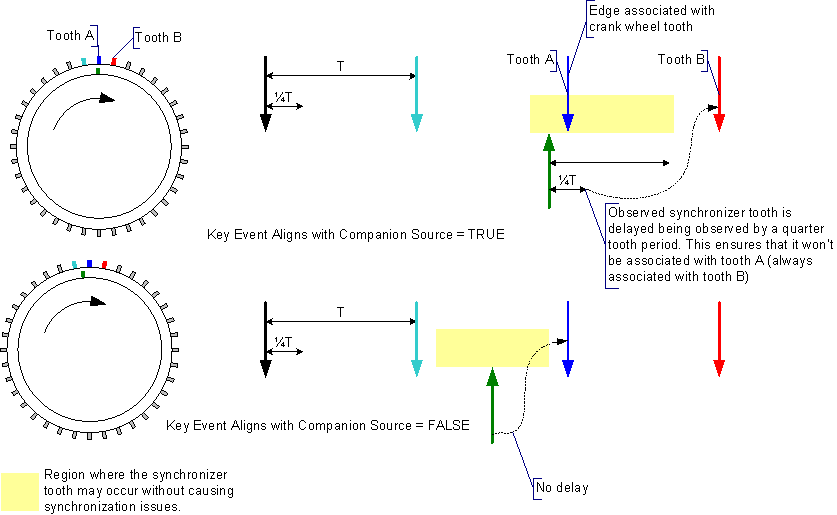
Whilst a tooth companion was used as an example, this attribute could also be used for a 6+1 companion that was providing a synchronizing event to a crank encoder that had 36 equidistant teeth. Here the Key Event Aligns with Source attribute of the 6+1 source definition would be checked (true) or unchecked (false) based upon whether the 6+1's key aligned with the crank teeth or not.
Synchronize Slip can also be used to manage an equidistant absolute source that uses a synchronizing companion that must deal with alignment.
| Copyright 2010-2014 Woodward Corporation. All Rights Reserved. | Visit Us: mcs.woodward.com |