 |
|
|
Flexible Encoder sources reference a pattern. This block defines such patterns. Either an XML style encoder pattern definition or a runtime version can be declared with this block. The pattern definition gives the application the flexibility to tailor the definition to take into account various nuances of the pattern's operation, including the strength of the pattern matching used to synchronize that pattern.
Use the Encoder Pattern Path Block to specify the location of custom XML pattern definitions.
Encoder Pattern Definition
motohawk_flexenc_lib
| Parameter Field | Values | Comments/Description |
|---|---|---|
| Name | Alpha-numeric text, quote enclosed | Choose a C-legal name for this encoder pattern. Blocks like the Absolute Source Definition Block will use this name to reference the encoder. |
| Pattern Type | Dropdown (XML or Runtime Defined) | Select the type of pattern to be defined. |
| Pattern | Alpha-numeric text, quote enclosed | The value of the DescriptiveName node of the pattern within the XML definition that is to be associated with this block. MotoHawk will associate the identified XML definition to this encoder definition block. Only applicable (and visible) when Pattern Type is XML. |
| Define Enumeration Order | Check Box | Check to allow the application to control the order that Flexible Encoder patterns are enumerated by the system. This can be useful when using calibration tools that deal directly with the value rather than the enumeration. Controlling the enumeration order for all patterns in the model will ensure that the same value is always associated to the same pattern. |
| Order | numeric | This value controls how Flexible Encoder patterns are enumerated. A low value will enumerate before another pattern that has a higher value. Those patterns that have not checked the Define Enumeration Order will be considered before those patterns that do have Define Enumeration Order checked. |
| Parameter Field | Values | Comments/Description |
|---|---|---|
| Runtime Pattern Type | Dropdown (NX, N minus M) |
Select the style of runtime pattern to be defined. Only available for edit when Pattern Type is Runtime Defined. |
| Maximum number of equidistant teeth | Integer greater than 1 |
Defines the maximum number of teeth that this pattern needs to account for. Only available for edit when Pattern Type is Runtime Defined. |
| Number of equidistant teeth | Integer greater than 1 |
The initial instance of the pattern will be defined to support this many teeth. Checking Use Calibration will expose this parameter to calibration. Only available for edit and exposed to calibration when Pattern Type is Runtime Defined. |
| Number of missing teeth | Integer greater than 0 |
Defines the number of missing teeth (M) to be used by an N minus M pattern definition. This attribute is only visible when the Runtime Pattern Type is N minus M. Checking Use Calibration will expose this parameter to calibration. Only available for edit and exposed to calibration when Pattern Type is Runtime Defined. |
| Key tolerance type | Dropdown |
Defines whether a symmetrical or an asymmetrical key tolerance will be employed by the pattern. This attribute is only visible when the Runtime Pattern Type is N minus M. |
| Key tolerance | Floating point value between 0.0 and 4.0 |
Defines the equivalent of <DefaultKeyTolerance> that will be used with the missing tooth key for this pattern. The runtime
equivalent of 60 minus 1 has a missing tooth key of 2.0, which equates to the number of missing teeth plus 1. The flexible
encoder would detect the missing tooth region if a tooth period ratio between 1.5 and 2.5 was observed when the Key tolerance was set to 0.5. This attribute is only visible when the Runtime Pattern Type is N minus M and the Key tolerance type is symmetrical. Checking Use Calibration will expose this parameter to calibration. Only available for edit and exposed to calibration when the Pattern Type is Runtime Defined. |
| High key tolerance | Floating point value between 0.0 and 4.0 |
Defines the equivalent of <DefaultKeyToleranceHigh> that will be used with the missing tooth key for this pattern.
The runtime equivalent of 60 minus 1 has a missing tooth key of 2.0, which equates to the number of missing teeth plus 1.
The flexible encoder would detect the missing tooth region if a tooth period ratio between 1.5 and 2.6 was observed if the
High key tolerance was set to 0.6 and the Low key tolerance was set to 0.5. This attribute is only visible when the Runtime Pattern Type is N minus M and the Key tolerance type is asymmetrical. Checking Use Calibration will expose this parameter to calibration. Only available for edit and exposed to calibration when the Pattern Type is Runtime Defined. |
| Low key tolerance | Floating point value between 0.0 and 4.0 |
Defines the equivalent of <DefaultKeyToleranceLow> that will be used with the missing tooth key for this pattern.
The runtime equivalent of 60 minus 1 has a missing tooth key of 2.0, which equates to the number of missing teeth plus 1.
The flexible encoder would detect the missing tooth region if a tooth period ratio between 1.5 and 2.6 was observed if the
High key tolerance was set to 0.6 and the Low key tolerance was set to 0.5. This attribute is only visible when the Runtime Pattern Type is N minus M and the Key tolerance type is asymmetrical. Checking Use Calibration will expose this parameter to calibration. Only available for edit and exposed to calibration when the Pattern Type is Runtime Defined. |
| Autogenerate halfcycle attributes for pattern | Checkbox |
Checking this box will let MotoHawk calculate the halfcycle attributes. Such attributes are only needed when the N minus M pattern
is to be used on a cam, which is not a typical configuration. Autogenerated values are not exposed in the calibration. This attribute is only visible when the Runtime Pattern Type is N minus M and is only available for edit when the Pattern Type is Runtime Defined. |
| ClrHalfCycleTooth | Integer (0..Max number of equidistant teeth -1) |
Allows the developer to specify the equivalent value of <ClrHalfCycleTooth> for an N minus M pattern when
Autogenerate halfcycle attributes for pattern is not checked. This attribute is only available for edit when the Pattern Type is Runtime Defined. |
| SetHalfCycleTooth | Integer (0..Max number of equidistant teeth -1) |
Allows the developer to specify the equivalent value of <SetHalfCycleTooth> for an N minus M pattern when
Autogenerate halfcycle attributes for pattern is not checked. This attribute is only available for edit when the Pattern Type is Runtime Defined. |
| Parameter Field | Values | Comments/Description |
|---|---|---|
| Use Calibration Settings | Check Box | Some pattern attributes may support calibration (defined by the XML definition). Check if the application is to define the grouping and access privileges of those calibrations. |
| Read Access Level | 0-8 | Only visible when Use Calibration Settings is checked. Sets security level 1 lowest, 8 highest, for user access to read pattern definition data that supports calibration. A setting of zero indicates unsecured access is allowed. This setting will override the ReadValue setting that may be defined in the XML definition. |
| Write Access Level | 0-8 | Only visible when Use Calibration Settings is checked. Sets security level 1 lowest, 8 highest, for user access to write pattern definition data that supports calibration. A setting of zero indicates unsecured access is allowed. This setting will override the WriteValue setting that may be defined in the XML definition. |
| Calibration Group String | Alpha-numeric text, single-quote enclosed | Only visible when Use Calibration Settings is checked. Determines folder name and hierarchy as displayed in the calibration tool for any pattern definition attributes that support calibration. Use the "|" character between folder names to delineate subfolder structure. |
A Flexible Encoder XML encoder pattern definition must contain the following nodes within an < Encoder > node (unless the node is marked as optional):
Some XML pattern attributes can be configured to support calibration.
Name is typically matched to the file name and is optional.
DescriptiveName identifies this encoder pattern definition to MotoHawk. This name should be unique for all the encoder patterns supported by a model. MotoHawk does provide some default encoder definitions and this could be grown over time. There will never be a namespace clash if the encoder definitions that are authored by the developer prefix the value of DescriptiveName with 'custom'.
Enter the value of the DescriptiveName within Pattern block entry to have the MotoHawk block reference this encoder pattern definition.
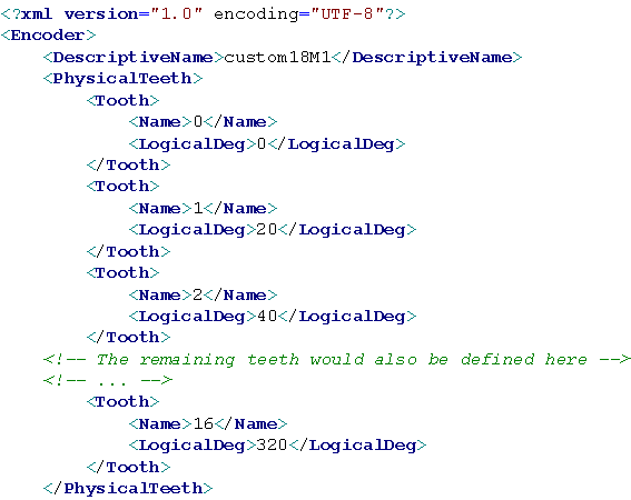
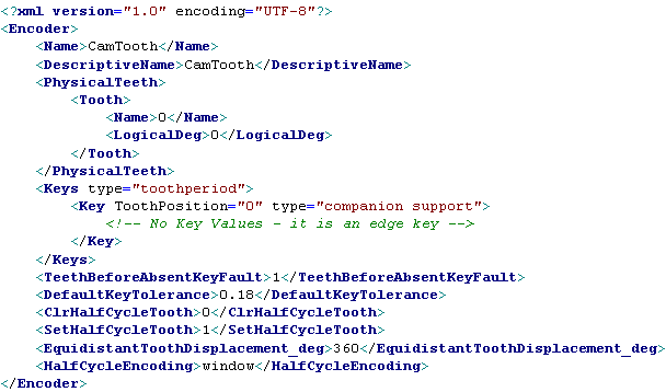
PhysicalTeeth houses the definition of the encoder pattern's tooth arrangement. Each tooth should have a Name and a LogicalDeg node. Optional attributes include WidthDeg.
Name is the tooth name and by convention is a number that starts at zero and increments with each definition.
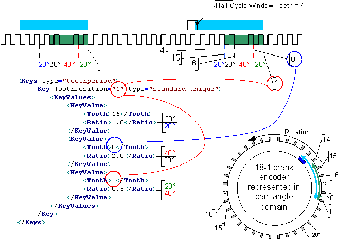
LogicalDeg defines the angle about the wheel relative to tooth zero (which is zero degrees) that the synchronous edge of the pulse train that would result when that tooth was observed. The synchronous edge is set by the Sync Polarity a source block and should correspond. Convention dictates that tooth zero should be selected to be the start of a series of similar tooth definitions. In the following example, where an 18 minus 1 pattern is defined, tooth zero is identified as the first tooth after the missing tooth. This ensures that all of the teeth have the same spacing from one another, which helps optimize internal performance.
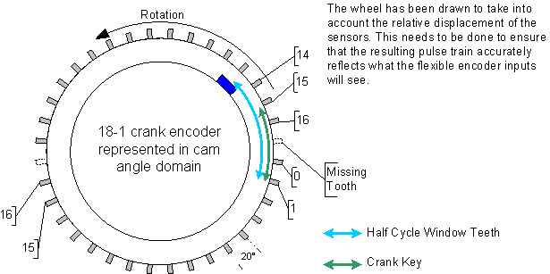
What follows is a partial definition of the 18 minus 1 crank encoder source depicted in the diagram. Note that the diagram has been drawn in the cam angle domain so that it can be used to explain the relationship between a cam encoder source and a crank encoder source (which rotates twice for a single rotation of the cam). The 18 minus 1 crank encoder pattern does not have two missing teeth. It has just be drawn twice to account for the two rotations that the crank source will undergo for a single revolution of the cam source.
An optional attribute, the <WidthDeg> node is used by the Flexible Encoder Output to specify the width of a tooth. Note that specifying a <WidthDeg> that is not uniform can result in the consumption of additional resources. Only the LogicalDeg node is important for an encoder source to interpret an encoder pattern.
This attribute defines the approximate equidistant tooth displacement of the encoder pattern being defined. The 18 minus 1 encoder wheel has an EquidistantToothDisplacement_deg of 20 degrees. This attribute is used to assist the pulse scheduling engine when this encoder pattern is in use. Some encoder patterns, like a tooth cam, are not used for pulse scheduling. A pattern like a tooth cam is a companion pattern that may only be used to provide half cycle information. However it still constitutes a pattern and as such this node is still supported, it would just have a value of of 360.
The value is optional. MotoHawk will calculate the equidistant tooth displacement by identifying what the most common delta displacement is and using that value.
Keys define the key(s) for an encoder pattern. These would be identified by the developer. A key is a pattern that is used by the flexible encoder system to facilitate pattern synchronization. Pattern synchronization needs to occur before the encoder system can associate each observed tooth to a specific angle on the encoder wheel. The flexible encoder observes the input signal(s) and searches that signal for a key(s). There can sometimes be more than one.
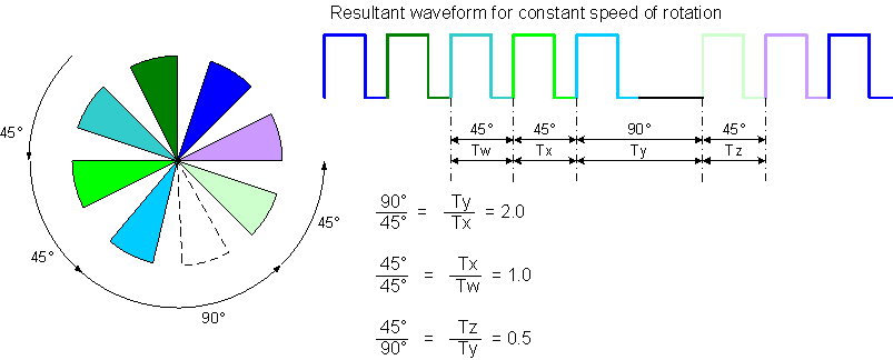
A Key is constructed from a sequence of Ratio values. A ratio of tooth displacements is invariant for constant speed of rotation, regardless of the speed of rotation, and thus allow variations in tooth to tooth displacement to be identified. Consider a tooth that is removed from a wheel of equidistant teeth (commonly referred to as a missing tooth pattern). The missing tooth provides a synchronization marker because it uniquely identifies a point on the wheel. The ratio of angle displacements just before and after the missing tooth will be 1.0, 2.0 and 0.5. Neighbouring teeth are separated by the same displacement and so will have a ratio of 1.0. The ratio between the missing tooth region and the previous equidistant tooth will be 2.0, whilst the first tooth after the missing will have a ratio of 0.5 (because the displacement of this tooth when compared to the previous tooth is half). The encoder system can calculate displacement ratio by measuring the time taken to traverse the teeth. The time taken to traverse a displacement is proportional to displacement for constant speed of rotation so tooth displacement ratios can be inferred by taking the ratio of neighbouring tooth periods (the time observed between teeth). Thus the encoder system could search for a ratio of 2.0 and know that the tooth after the missing tooth had just occurred. Alternatively it could search for 1.0 followed by 2.0 as this is also unique. DefaultKeyTolerance allows constance a speed of rotation to be assumed by installing a symmetrical window of acceptable ratio values. DefaultKeyToleranceHigh and DefaultKeyToleranceLow allow an asymetrical window of acceptable ratio values to be defined.
Note that whilst the key "2.0" or the key "1.0, 2.0" are both unique, a system could not define both of these keys because a unique key shall not contain the entirety of another key. It would also serve no purpose to detect both keys.
The width of a tooth can also be used for pattern detection. Thus Keys may have a type that is either toothperiod or pulsewidth. Use toothperiod when the Ratio is constructed from adjacent tooth periods. Use pulsewidth when the Ratio between the tooth period and the tooth's width is to be used to construct the key. All the defined keys will interpret Ratio in the same manner.
A pattern may support more than one Key and there are also different types of keys.
A key is constructed from a sequence of KeyValue that are housed within a KeyValues node. Each KeyValue has a Tooth and a Ratio node.
The most common key type are those that are used by the encoder system to calculate the position on the wheel. In other words, the encoder is able to determine the position of the last observed tooth about the wheel when an entire key match has occurred.
ToothPosition is used to define the tooth position a particular key will detect. The diagram below illustrates a 3 tooth key. Note that ToothPosition has the value of 1, which corresponds to the last Tooth in the key. So this key detects tooth position 1. The encoder system knows that it has just observed tooth #1 whenever it observes this key on this encoder source. It knows this because the type is standard unique. Standard keys provide positional information. A standard key that is unique means that this key definition only exists once within the pattern. The construction of this key and the use of ratio is further detailed here. ToothPosition is optional/meaningless if the type is not a standard key.
| type= | Definition |
|---|---|
| standard unique | Standard keys provide positional information. A standard unique key shall only exist once within the pattern and thus will convey absolute position if that key is ever observed. |
| standard semi unique | A standard semi unique key provides positional information, but is not unique. The 3x20M2 pattern contains a semi-unique key. A semi-unique key requires a synchronizing source to exist that will provide an event that can uniquely identify one of the semi-unique keys. See here for an example. A standard semi unique key implies that there are multiple keys that are the same (there are 3 instances of the semi-unque key in the 3x20M2 example). However only one instance of the key would be defined and it's ToothPosition would be configured for the semi-unique key instance that will be marked as unique by a companion synchronizing source. |
| signal inverted | A signal inverted key does not provides positional information. Instead it is looking for a pattern that may occur if the sensor of the encoder source is not connected correctly. It would be used as a diagnostic. See here |
| companion support |
A companion support key does not provides positional information. Instead it is used to convey an occurrence event that another source is looking for.
A single tooth synchronizer pattern would utilize a companion support key to signal a source with semi unique keys
when it occurred so that one of those semi-unique keys could be marked as unique (because it is the first to occur after the companion support key). Attempting to switch to a source that references a pattern that is used for companion support will fail. |
A Key that has no values is referred to as an edge key. Every observed tooth of an edge key is considered to be a key. A tooth cam like the example below or a 36 equidistant tooth wheel would utilize such keys. The 36 tooth wheel would supply positional information and so its key type would be standard semi unique rather than the companion support that can be seen in the ToothCam example below.
This is a convenient marker to associate a key value entry to a PhysicalTeeth Name entry. The circled values in the diagram below illustrates the relationship between a physical tooth and the key value.
Ratio defines the expected matching relationship at this tooth. The relationship always relates to measurements that occur prior to observing the synchronous edge of the signal (which corresponds to a LogicalDeg entry).
When toothperiod matching is in use the ratio is defined as the angular advancement of the tooth previous to the tooth under examination divided by the angular advancement from the previous tooth to the tooth under examination. The diagram above highlights this with colors. Consider the toothperiod based Ratio determination for Tooth#0. Tooth#0 is the first tooth after the missing tooth and is 40 degrees advanced from the the previous tooth (because there was a missing tooth and each tooth is nominally displaced 20 degrees apart). The tooth previous to the tooth under examination (Tooth#0) is Tooth#16 and it is 20 degrees advanced from the tooth previous to it (Tooth#15). Therefore the Ratio is 2.0.
Pulsewidth based keys use a ratio that is based upon the width of the tooth divided by the degrees of advance from the previous tooth. The synchronous edge plays a very important part in the calculation of the ratio. If the synchronous edge is the falling edge then the high portion of the signal is used to calculate the ratio (signal A in diagram below). If the synchronous edge is the rising edge then the low portion of the signal is used to calculate the ratio (signal B in the diagram below).
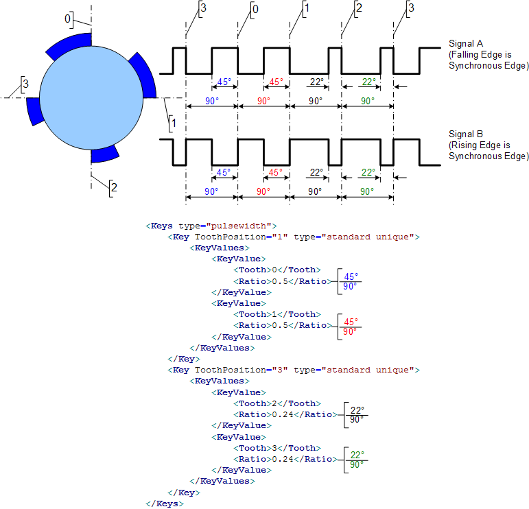
The ratios of Pulsewidth based keys should always be smaller than 1.0. Also note that there can be more than one key.
The example pattern is sometimes referred to as PWM cam. Type at the MatLab command line motohawk_flexencoder_project('FESamplePWMCam','Cnk_60M2_Cam_PWM') to create a sample model on the current path that uses this style of encoder pattern.
Ratios can only be defined with a resolution of 0.0625 and the internal calculation of observed ratios can only be resolved to within 0.0625 (and will truncate). These limitations with resolution should be considered when constructing key values.
Standard keys convey position and are thus expected to always be observed. An absent key fault or missed key fault results when an expected key is not observed. An absent key is detected by noting how many encoder source teeth have been observed since the last standard key was observed. The TeethBeforeAbsentKeyFault attribute allows the developer to define this value for their pattern.
An appropriate value for this attribute would be 19 if the 18M1 example pattern was in use. The encoder system expects to observe the missing tooth key once per revolution and there are 17 physical teeth per revolution. However rotation may initially start within the key, which is 3 teeth wide for this particular version of the 18M1 pattern. The key won't match unless the entire key is observed and thus starting within the key will not result in a match. Therefore it's possible to legally observe 17+2 teeth and still not have observed the key.
For the 4 toothed pulsewidth the value would be 3. There is more than one key so a key should always have been observed before a full rotation has occurred.
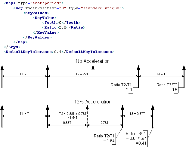
Most key pattern matches are based upon a sequence of ratio matches. These are specified as an absolute value, yet successful matches will require an acceptance band to be defined because the signal will have variance. The <DefaultKeyTolerance> attribute defines this value. Plus or minus <DefaultKeyTolerance> is applied to each key value to create an acceptable key range. The value saturates to zero or to a maximum. Thus the lower acceptance value for a ratio value of 0.25 when used with a <DefaultKeyTolerance> value of 0.3 would be 0.0.
The following missing tooth example illustrates how the tolerance works and why it is needed. The simple missing tooth key looks for a ratio of 2.0. Under acceleration this ratio won't be observed yet the missing tooth has clearly occurred. To reliably detect this key requires a tolerance value of 0.4 to be used. This creates an acceptance window of 1.6 to 2.4, which 1.64 falls within. If the tolerance had been 0.3 then the observed ratio of 1.64 would not have qualified as a legal key match because it falls outside the 2.3 to 1.7 window.
<DefaultKeyToleranceHigh> and <DefaultKeyToleranceLow> allow the symmetrical <DefaultKeyTolerance> to be declared as an asymmetrical tolerance. The upper tolerance is defined by <DefaultKeyToleranceHigh> and the lower tolerance is defined by <DefaultKeyToleranceLow>. Both values should be positive. In the previous example <DefaultKeyTolerance> was defined to be 0.4 to give an acceptance window of 1.6 to 2.4. Setting <DefaultKeyToleranceHigh> to 0.5 and <DefaultKeyToleranceLow> to 0.4 for use in the example above would allow an asymmetrical acceptance window of 1.6 to 2.5 to be defined.
The <DefaultKeyTolerance> attribute should not be included in the XML definition if an asymmetrical tolerance is defined.
Some encoder sources can be used to provide halfcycle information. Such sources are located on a camshaft and are used to identify which halfcycle a particular engine revolution is associated to (the crank shaft rotates twice as fast as the camshaft). Therefore, from the perspective of an encoder pattern, any pattern could technically be utilized as a halfcycle source. In reality only certain patterns are capable of operating as a halfcycle source, but, so as to avoid having to distingish them, all patterns definitions are assumed to be capable and therefore they all shall support the following attributes:
This attribute specifies how a flexible encoder pattern encodes half cycle. There are three possible schemas, key state, pin state and windowed.
| HalfCycleEncoding | Description |
|---|---|
| state | Used when the pattern supports standard unique keys. Such patterns are able to synchronize themselves without assistance from a companion source. Therefore, once synchronized, the source can be queried for its current position and that position used to indicate whether the system is currently in the first or second half of the cycle. This decision is made using the ClrHalfCycleTooth and set SetHalfCycleTooth attributes. |
| pin | Used when the state of the sensor pin implies the halfcycle state. So a halfmoon sensor could use this style of encoding. To be valid the pin state must reflect the correct halfcycle for each standard unique key that is defined on the absolute source. For example, an 18M1 crank shaft encoder could utilize pin HalfCycleEncoding if the pin would be high around the missing tooth (where the key would likely be defined) for one rotation. pin HalfCycleEncoding is assumed to always be available to the encoder system, which implies that the pin state of the companion will always represent the halfcycle state when a standard unique key is observed on the absolute source that requires the halfcycle information. |
| window | Window encoding is used when the pattern does not support any of its own standard unique keys and the pin state of the pattern does not align with the keys of the absolute source that requires the halfcycle information. The 18M1 with tooth cam figure would utilize the window approach because a tooth cam can't support state or pin encoding. The window defines the region of teeth relative to the standard unique key of the crankshaft source. The 18M1 waveform highlights the halfcycle window. Note that the tooth cam pulse only occurs relative to every second missing tooth (because it rotates at half the speed). Importantly, window halfcycle encoding has been implemented such that it can only be utilized on companion source that has a single standard unique key. If the source in use has more keys than this then all but one of the keys should be deleted so that it will work with the window approach. |
These attributes are only used by a pattern that is going to be used to provide halfcycle information and the pattern uses a HalfCycleEncoding of state. The values defines the regions of the pattern that are considered to be in the first half of the cycle and the second half of the cycle. The regions are normally selected to describe approximately half of the pattern. It does not need to be exactly half. The source that is using the companion for half cycle information will only attempt to determine the the half cycle state when it observes a key. The described regions need only ensure that they differentiate one revolution from the other.
The shaded regions (yellow and blue) of the figure below encompass different revolutions of the crank and are thus valid. Values of 3 and 4 would be illegal because they would not allow one crank revolution to be distinguished from the other.
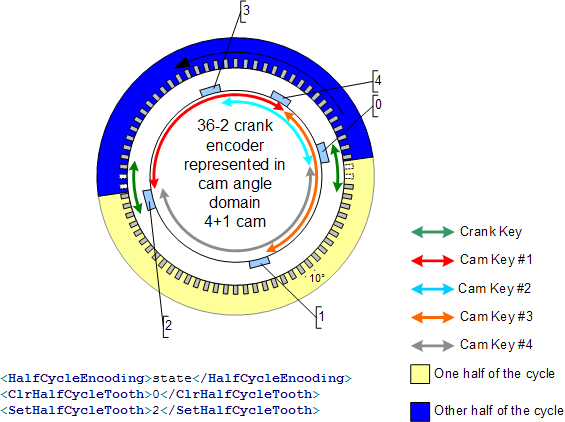
This attribute defines the teeth that represent the first half of the halfcycle. All teeth inclusive of the stated tooth but not including the SetHalfCycleTooth represent teeth in the first half of the cycle. A 5 tooth encoder with a ClrHalfCycleTooth value of 0 and a SetHalfCycleTooth of 2 defines teeth #0 and #1 as being in the first half of the cycle.
This attribute defines the teeth that represent the second half of the halfcycle. All teeth inclusive of the stated tooth but not including the ClrHalfCycleTooth represent teeth in the second half of the cycle. A 5 tooth encoder with a SetHalfCycleTooth value of 2 and a ClrHalfCycleTooth of 0 defines teeth #2, #3 and #4 as being in the first half of the cycle.
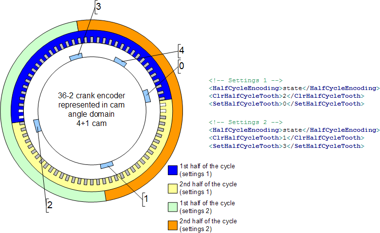
ClrHalfCycleTooth and SetHalfCycleTooth need to be tuned with care. Often a number of legal settings are possible, but some will have advantages over others. Two options are presented in the figure below. Settings 2 is equally as valid as Settings 1, but Settings 2 has some advantages.
The half cycle doesn't change state near the crank key for the Setting 2 configuration. This allows the possibility that the halfcycle companion could detect a loss error before it was queried to provide halfcycle state. The halfcycle state read by the crank encoder when it detected the missing teeth would not be correct if loss of the half cycle companion occurred between tooth #4 and tooth#0 for the Setting 1 configuration (because tooth#0 wouldn't be observed and so the past state would be maintained). With the Setting 2 configuration the state would still be correct when initially entering into the loss condition. The loss could be detected before state was next queried so the status quo would be maintained since a source in fault is never queried
Secondly, if the 4P1 pattern were being used in a Variable Cam Phaser arrangement, then the Setting 2 configuration must be used because the halfcycle state must remain consistent when queried. If the cam could move then it is conceivable that tooth #0 could move to be before or after the crank encoder's missing teeth. The Setting 1 configuration would report different halfcycle states depending upon whether tooth#0 occurred before or after the crank encoder's missing teeth, which wouldn't be the case for the Setting 2 configuration.
Some legal settings can also be less optimal when attempting to optimize synchronization time. See the halfcycle window discussion.
Some attributes of an XML pattern definition can be configured for calibration. The grouping and access levels of these attributes can be specified within the XML pattern definition. These settings can be overridden by checking the Use Calibrations Setting checkbox on the pattern definition block. Ultimately these settings are required if any of the pattern attributes are to support calibration, but whether that definition comes from the XML pattern or the block is a developer decision.
Determines folder name and hierarchy as displayed in the calibration tool for any pattern definition attributes that support calibration. Use "|" character between folder names to delineate subfolder structure.
Sets security level 1 lowest, 8 highest, for user access to read pattern definition data that supports calibration. A setting of zero indicates unsecured access is allowed.
Sets security level 1 lowest, 8 highest, for user access to write pattern definition data that supports calibration. A setting of zero indicates unsecured access is allowed.
Some aspects of an encoder pattern's XML definition can be configured for calibration. This gives the application the flexibility to define a few styles of patterns that can then be tuned via calibration after the software has been built. For example, an application could be designed to support an N teeth pattern using a single pattern definition rather than having to support N patterns.
Note that supporting pattern calibration will increase code space consumption compared to the equivalent build time defined pattern. A calibrated pattern also requires some RAM support where as build time defined patterns don't require any RAM support. A calibrated pattern, by their nature, will also consume calibration space.
The logical displacements of the physical teeth can be calibrated by defining the supported_teeth attribute and setting it to the number of teeth that the pattern is to support. The displacement values will be initialized using the Physical Teeth values supplied in the XML definition (when they exist).
The example below creates a 36 minus 2 XML pattern definition that could be configured for 60 minus 2 operation via calibration because the supported_teeth attribute is defined to be 58 (60 minus 2 has 58 physical teeth).
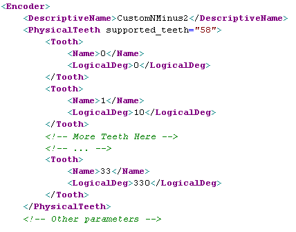
Two calibration parameters are created when supported_teeth is defined.
[Name] refers to the name the pattern definition block gave to the referenced XML pattern definition.
The EquidistantToothDisplacement_deg is an optional attribute. It is not used when PhysicalTeeth support calibration. Instead MotoHawk will calculate this value by determining what the most common delta tooth displacement is for the defined pattern.
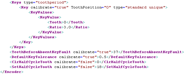
The generic N minus 2 pattern example above had no need to define a calibrated key because the key was always the same (a 3.0 ratio key could be used irrespective of whether the pattern had 34 teeth or 58 teeth because the number of missing teeth does not change and the ToothPosition is zero in either case). However the key needs to support calibration if the generic pattern was to support an N minus M pattern style because now the ratio must change. Other pattern styles, like those with keys to detect an extra tooth, may also need to calibrate the ToothPosition attribute.
Key calibration is enabled by setting the optional calibrate attribute of the Key attribute to true. Below is an example of a double missing tooth key that has been configured to support calibration.
Patterns with multiple keys could define some keys to support calibration and have others not support calibration
Up to two calibration parameters are created when calibrate is true.
[Name] refers to the name the pattern definition block gave to the referenced XML pattern definition and [order] refers to the order of the Key definition within the XML definition.
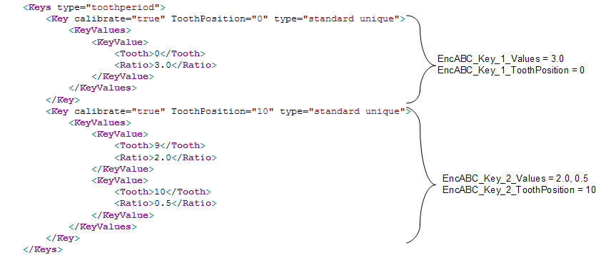
The following illustrates the Keys portion of an XML pattern definition that is referenced by a Flexible Encoder Pattern Definition block that named the encoder pattern 'EncABC'
Setting the calibrate attribute of either the ClrHalfCycleTooth or SetHalfCycleTooth attribute to true will enable both of these attributes for calibration.
Setting the calibrate attribute of DefaultKeyTolerance to true will enable calibration of this attribute.
Setting the calibrate attribute of either DefaultKeyToleranceHigh or DefaultKeyToleranceLow to true will enable calibration of both of these attributes.
Setting the calibrate attribute of TeethBeforeAbsentKeyFault to true will enable calibration of this attribute. This value typically needs to support calibration when Physical Teeth also support calibration.
Runtime defined patterns sacrifice flexibility in their definition so as to allow the controller to create an encoder pattern at runtime (during controller start-up). The pattern is constructed based upon the runtime pattern type and some core data (such as how many teeth it has).
Runtime defined patterns will consume more resources than an XML based pattern because the pattern definition is constructed at runtime rather than at build time. Such pattern definitions will therefore consume more RAM than their XML equivalent.
Runtime patterns can simplify the support, through calibration, of multiple patterns that are very similar. The support is simplified because the patterns can be abstracted to the calibration through a small set of data items. For example, a model could support a generic pattern definition that would be used to describe all equidistant encoders using just two calibrated variables.
An NX encoder pattern has N teeth distributed uniformly about the wheel. Thus each tooth is equidistant from the next tooth and the previous tooth.
An N minus M encoder pattern has N teeth distributed uniformly about the wheel with M adjacent teeth then removed. Thus each tooth is equidistant from the next tooth and the previous tooth except around the missing tooth region.
A runtime N minus M pattern would define the equivalent of the following at runtime:
<Keys type="toothperiod">
<Key ToothPosition="0" type="standard unique">
<KeyValues>
<KeyValue>
<Tooth>0</Tooth>
<Ratio>M+1</Ratio>
</KeyValue>
</KeyValues>
</Key>
</Keys>
<DefaultKeyTolerance>KeyTolerance</DefaultKeyTolerance>
| Copyright 2010-2016 Woodward Corporation. All Rights Reserved. | Visit Us: mcs.woodward.com |