 |
|
|
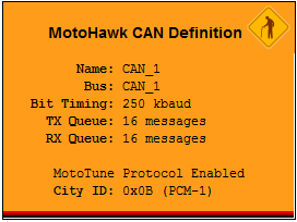
This MotoHawk™ block selects which CAN bus to initialize and define. CAN_1 is available on most ECUs, but CAN_2 and CAN_3 are available on some. See specific ECU datasheet for CAN information.
CAN Definition
MotoHawk_lib/CAN Blocks
Each CAN receive block includes an ID, which is used in combination with the mask. Only the bits set to 1 in the mask for the corresponding buffer are compared when detecting a received message.
Specify Baud Rate under Bit Timing, as required for module communication; typical is 250k baud. Or select "User Defined" for meeting customized, special-case protocol and CAN connection requirements.
Check Install MotoTune Protocol (recommended) to install MotoTune protocol for use over the given CAN interface.
| Parameter Field | Values | Comments/Description |
| Name | Alpha-numeric text, single-quote enclosed | Name of CAN definition. Should be unique and C-legal (no special characters such as spaces, dashes, commas, though underscore allowed. Other MotoHawk blocks may reference this CAN channel by the name entered in this field. For instance, the user could define the name of CAN 1 as ‘Body_Bus’ while naming CAN 2 ‘Engine_Bus’. |
| CAN Resource | CAN_1, CAN_2, CAN_3 | Specify which CAN Channels to initialize. |
| Bit Timing | Drop-down list of baud rates, or User Defined |
Specify Baud Rate as required for module communication, typical is 250k
baud. Or select "User Defined" if necessary, for meeting custom, special-case
protocol and CAN connection requirements. NOTE: Most applications use one of the pre-defined baud rates, usually 250k. Only advanced users with specific needs are advised to attempt to utilize a User Defined baud rate. |
| Transmit Queue Size | Numeric | Specify the number of messages held in the transmit queue. For, most applications the default of 16 is adequate. Applications sending many CAN messages may require a larger value. |
| Prescaler | MatLab Numeric expression | For "User Defined" Bit Timing, set the prescaler (fractional or proportional type value) for data value. |
| Propagation Segment | 0-7 | For "User Defined" Bit Timing, set the size of the Propagation Segment. |
| Phase Segment 1 | 0-7 | For "User Defined" Bit Timing, set the size of the Phase Segment 1. |
| Phase Segment 2 | 0-7 | For "User Defined" Bit Timing, set the size of the Phase Segment 2 |
| Resynchronization Jump Width | 0-3 | For "User Defined" Bit Timing, set the size of the Resynchronization Jump Width. |
| Install MotoTune Protocol | Check Box (enable) | Install MotoTune protocol to enable MotoTune to communicate with the module over the selected CAN channel. This is required for online displays and online calibration. Note that after a module is programmed with an application that DOES NOT contain the MotoTune protocol, a boot key must then be used when reprogramming the module. |
| City ID | hex2dec('value') | Define the City ID that MotoTune will use to communicate with the module. On a CAN bus with multiple MotoHawk enabled modules, MotoTune can communicate with each module by addressing their respective City ID’s. Therefore, each module on a bus MUST have a unique City ID. See MotoTune documentation for help on setting up MotoServer to communicate with multiple modules. |
| City ID Access Level | 0-8 | Sets security level 1 lowest, 8 highest, for user access to City ID. A setting of zero indicates unsecured access is allowed. Users having a MotoTune license with an access level lower than that specified in this field will not be able to communicate with the module via MotoTune. For instance, a user with a MotoTune license access level of 2 will not be able to communicate with a module programmed to require an access level of 3. The default access level for MotoTune licenses is 4. Contact Woodward sales to obtain licenses with lower access levels. |
| MotoTune Group String | Alpha-numeric text | Determines Folder name and hierarchy as displayed in MotoTune. Use "|" character between folder names to delineate subfolder structure. |
| Copyright 2009-2014 Woodward Corporation. All Rights Reserved. | Visit Us: mcs.woodward.com |