
Flexible Encoder Get Average Cycle RPM
Recovers the Average Cycle RPM of the active encoder source of the referenced Flexible Encoder System. Use in conjunction with Cycle RPM Trigger block to read an updated RPM.
Block ID
Get Cycle RPM
Library
motohawk_flexenc_lib
Description
Average Cycle RPM
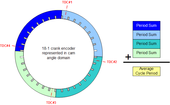
Average Cycle RPM is calculated using a measured cycle period. On each RPM sample point that has been defined for the active encoder source the appropriate time span is updated. So in the simple figure, the blue period always updates just before TDC#1, the light blue period updates just before TDC#2, the cyan period updates just before TDC#3 and so forth. The average cycle RPM is calculated based upon the yellow Average Cycle Period, which is the sum of the acquired periods at the time the RPM was requested.
Instant RPM is returned if the active encoder source does not have any sample points defined. Note that a pseudo encoder is treated as an independent source and as such does not have any RPM sample points defined for it.
RPM Sample Points
Each RPM sample point resolves to an encoder tooth. The tooth that is closest to the requested sample angle, but before the position will be selected when the sample point does not align directly with a tooth. Patterns that revolve twice per cycle are considered to have twice as many teeth as defined by the pattern. The 18 minus 1 example above would transform a sample point array of 0, 180, 360, 540 to tooth #0, #9, #17, and #26. This assumes tooth#0, which is always encoder TDC, has been defined to be the first tooth after the missing tooth. Tooth #17 is the first tooth in the second revolution of the pattern.
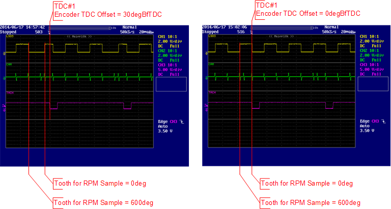
Sample points are defined relative to engine TDC. Therefore the value supplied for Encoder TDC Offset will impact what encoder tooth will be associated with a RPM sample point. The 18 minus 1 example illustrates an encoder TDC offset of -10degBfTDC#1 and so the closest tooth to a sample point will align with the encoder pattern definition. The figure below was created by monitoring with a scope the model created by the motohawk_flexencoder_project script with an encoder_system_type of 'Cam_6P1'. Note that different teeth are selected based upon whether 30deg or 0deg is used for the encoder TDC offset.
The Cycle RPM Trigger block will not function as expected if each RPM sample point does not also resolve to a different encoder tooth (because ultimately RPM is calculated by observing the time between teeth). Therefore there should never be more sample points in use than there are encoder teeth in the pattern.
Block Parameters
| Parameter Field | Values | Comments/Description |
|---|---|---|
| Reference System Name | Alpha-numeric text, quote enclosed | The name of the Flexible Encoder System Block that this block is to recover the RPM from. This attribute may be hidden (not visible) if the implementation is implicitly inferring the name. |
| Output Resolution | Drop Down List | The default resolution is 1 RPM and the output data type is uint16. When the resolution is selected to be 1/256, the output is RPMx256 and the output port width will be uint32. . |