112-pin Module Family
There are three ECUs in the 112-pin family - the ECM-5554-112-0904 (PCM-09), ECM-5644A-112-064-1400 (PCM112-14), and the ECM-5644A-112-120x (SECM-112).
Contents
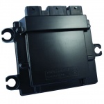
ECM-5554-112-0904
Hardware Features
- Microprocessor: Motorola MPC5554, 80 MHz
- Memory: 2MB Flash, 64K RAM, + 32K Cache, 32K EEPROM
- Calibratible Memory: 512k (256k x2) RAM
- Operating Voltage: 9-16VDC, 24V (Jump start), 4.5V (Crank)
- Operating Temperature: -40° to 105° C
Inputs
- VR and Digital Engine Position Sensor (crank and cam) Inputs
- 33 Analog Inputs
- 4 Oxygen Sensor Inputs
- 3 Speed (digital) Inputs
- 2 Knock Sensor Inputs
- 1 Emergency Stop Input
Outputs
- 8 Injector (high impedance) Outputs
- 8 Electronic Spark Trigger (5V) Outputs
- 1 Tachometer or Link Interface Output
- 14 Low Side Outputs
- 1 Main Power Relay Driver Output
- 2 H-Bridge Outputs
Datalinks
- 3 CAN buses
- 1 RS485 Channel
FAQ
Is it possible to fire an injector without an encoder input?
When the application is not synchronized to an engine or crank wheel, the application can still make use of PSP capabilities.
- Option 1
- Create a Pseudo encoder using the Flexible Encoder blocks, set desired pulse frequency (rpm)
- Utilize your application logic to calculate a desired pulse width
- Request PSP to deliver an application determined pulse width via a standard Injector driver block (E.g. MultiplePSP)
- Option 2
- Create a Pseudo encoder using the Flexible Encoder blocks, no need to enable rpm
- Utilize your application logic to calculate a desired pulse width
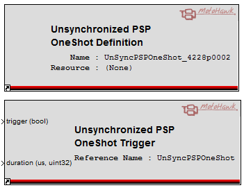
- Drive output using the unsynchronized PSP. This allows pulses that are PSP in nature to be driven with only a pseudo encoder instantiated, and can be fired as the application requires.

Note that there are two other one shot behaviors available for the injector pins, but these have a drawback that the injector diagnostics would not be available. These diagnostics are only possible when the injector is operating in a PSP (synchronized pulse) mode that is typically used with an engine encoder.
GCM-5554-112-1001
The 112 pin General Control Module is the same as the ECM-5554-112-0904 above except with engine related IO replaced by analog inputs for general control purposes.
The following are the changes from ECM-5554-112 to GCM-5554-112:
- pins EST1 to EST8 change to AN34 to AN41 (3k-ohm pull-down, with a diode drop between pull-down resistor and ground).
- AN1, AN2, AN3, AN26, AN27, AN28 change from 51.1k pull-down to 220k-ohm pull-down.
- GCM-5554-112 does not populate the internal CAN3 termination: all 3 CAN buses are un-terminated internally.
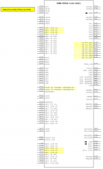
Differences between the ECM-5554-112-0904 and the GCM-5554-112-1001 are also shown in the diagram below.
1751-6456 (PROD) 1751-6457 (DEV)
ECM-5644-112-1400 PCM112-14
Hardware
- 112-pin platform
- Main micro: MPC5644A, 120 MHz
- Auxiliary micro: S12G128, 24MHz
- Memory: 4M flash, 192K RAM, 16K external serial EE; S12G128, 128k flash, 8K RAM, 4K EE
- Operating Voltage: 8–16 Vdc,36 V (jump start), 5.5 V (crank)
- Operating Temperature: –40 to +105°C
Inputs
- 4 switch to GND, 1 switch to BATT
- VR or digital crank position sensor
- VR or digital CAM position sensor
- Up to 23 analog inputs
- 2 knock sensors
- Up to 4 switching oxygen sensors
- Up to 2 wide-range oxygen sensors
Outputs
- 8 injector drivers
- 4 Ignition Coil
- 2 10A H Bridge with current sense
- Up to 15 low side
- 3 5V sensor supplies, 1 @ 50 mA, 2 @ 100 mA
Communications
- 3 CAN 2.0b buses
- 1 RS-485 bus
ECM-5644-112 SECM-112
This is our newest module! Check out features and additional information on the SECM112 wiki page.
These are Preliminary Specifications and subject to change.
Hardware
- 112-pin platform
- Main micro: MPC5644A, 120 MHz
- Auxiliary micro: S12G48, 24MHz
- Memory: 2M flash, 128K RAM, 32K external serial EE; S12G: 48K flash, 4k RAM, 1.5K EE,
- Calibratible micros: MPC5644A, 4M flash, 192K RAM; S12G128, 128k flash, 8K RAM, 4K EE
- Operating Voltage: 8–32 Vdc,36 V (jump start), 5.5 V (crank)
- Operating Temperature: –40 to +105°C
Inputs
- VR or digital crank position sensor
- VR or digital cam position sensor
- Up to 31 analog inputs
- Up to 4 switching oxygen sensors
- Up to 2 wide-range oxygen sensors
- 2 knock sensors
- Up to 6 speed inputs
Outputs
- 8 injector drivers (6 peak/hold capable)
- 8 ignition coil drivers or spark timer outputs
- 1 tachometer driver
- Up to 19 low-side drivers (1 w/current sense)
- 1 main power relay driver
- 2 H-bridge drivers w/current sense
- 3 sensor supplies (2-5V, 1-12V)
Communications
- 3 CAN 2.0b buses
- 1 RS-485 bus


