MotoTune:Quick Guide
Contents
- 1 MotoTune Installation
- 2 MotoServer Port Configuration
- 3 Programming an ECU
- 4 Creating a Program File From a Calibration
- 5 Transfer Upgrade Cal Into New Software Level
- 6 MotoTune Connection Troubleshooting
- 7 Logging Data Using MotoTune
- 8 Display Sheets and Pages
- 9 Display Warning Limits
- 10 Reprogramming Using Boot Key
- 11 Changing City ID
- 12 Changing the Connection Baud Rate
- 13 Setting DLL file locations
- 14 Capturing a Communications Debug Log
MotoTune Installation
1. Install MotoServer from the MotoTron CD and follow instructions. The KVASER driver will install automatically
2. Install MotoTune from the MotoTron CD and follow instructions.
MotoServer Port Configuration
1. Install the MotoTune dongle in the USB port.
2. Install the Kvaser CAN tool in the other USB port. Computer will prompt you to install new drivers for the device.
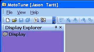
3. Open MotoTune and check that your company name appears in the upper left corner, which indicates that MotoTune has identified your license key in the dongle. The figure below illustrates MotoTune with my personal dongle installed. The name from your dongle will be different.
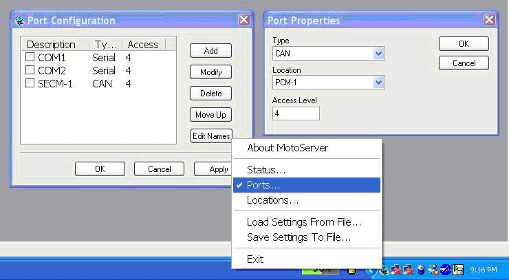
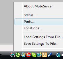
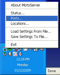
4. Next configure the MotoServer ports by right-clicking on the satellite in the lower right corner of the computer screen.
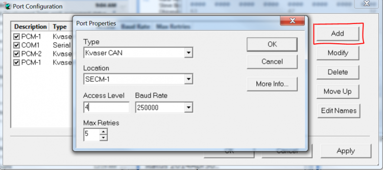
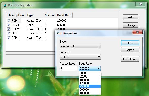
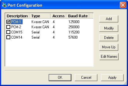
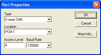
5. Selects Ports from the menu, and click the Add button in the Port Configuration dialog box. Set up the pull-down menus in the Port Properties dialog box like the figure below. Click the OK button in the Port Properties dialog box. Un-check all of the ports in the Port Configuration except for the PCM-1 port.
Programming an ECU
1. During the MotoTune installation, MotoTune created an ECUFiles folder on the c: drive of the computer, with various folders underneath. Place all .cal files in the Cals folder, .dis files in the Displays folder, .srz in the Programs folder, and .dll in the TDBDLL folder.
2. Install the correct ECU into the wiring harness and turn on key-power to the ECU.
3. In MotoTune, ensure that all calibration and display files are closed. Click the Program button and select the desired .srz file to program from the Programs folder.
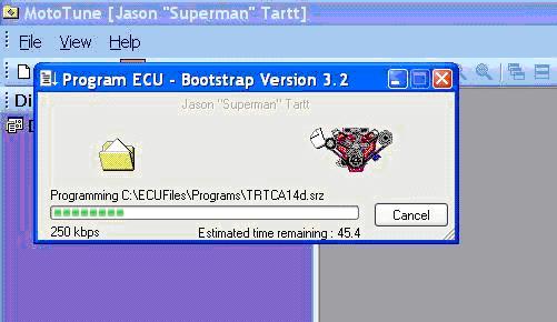
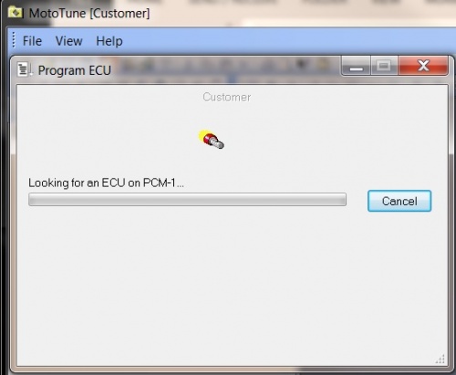
4. The following programming status bar should appear on your screen if PC is on-line with the ECU. If a programming error occurs, check for power to the ECU’s ECUP pins and ECU ground. Also check CAN connections based on block diagram of ECU.
Creating a Program File From a Calibration
1. Open the desired calibration offline.
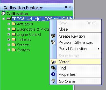
2. Right click on the calibration name and select Merge.
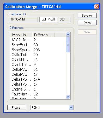
3. Select the production software .srz file into which you would like to merge the calibration. The software level must be the same as the calibration software level (first nine letters of the calibration). Select Open in the dialog box.
4. Type a new .srz file name into the window of the Calibration Merge dialog box and select Save As.
5. Save the new .srz into the appropriate folder on the computer.
6. Follow the instructions above for Programming an ECU to program the new .srz onto the production ECU.
Transfer Upgrade Cal Into New Software Level
1. Create a new cal from the new .srz file with File/New/Calibration From Programming File.
2. Select the correct new .srz and click Save.
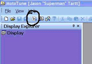
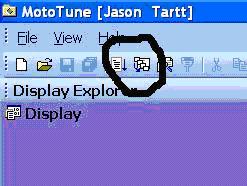
3. Click the Transfer Upgrade button shown below.
4. In the window, double click on the old cal file. Then double click on the new cal file created in steps 1. and 2.
5. Click the Start button, and note the differences listed in the Report. Sometimes cal maps do not transfer upgrade, therefore these maps will need to be transferred manually using copy and paste. Using the Save Report button to save and view the report later for manual upgrades.
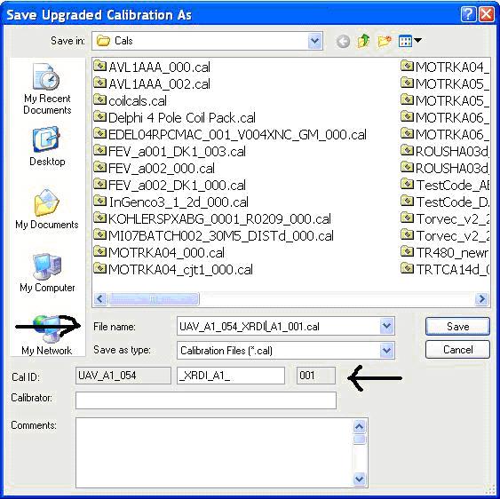
6. Click the Save As button and rename the calibration File Name such that it is the same as the Cal ID name.
7. Program the ECU with the new software.
8. Open the new, transfer upgraded cal and click yes when prompted to Sync the new cal.
MotoTune Connection Troubleshooting
1. With key-on, check for power at ECUP (pin F on the J-Box) and BATT, if applicable (pin A on the J-Box).
2. Check continuity between battery ground, the J-Box ground, and ECU ground.
3. Check for the correct polarity on CAN wires. On the 10-pin connector, pin J is CAN+ and pin K is CAN-.
4. Check for the appropriate port set-up under the Moto-Server icon.
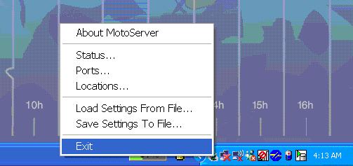
5. If all of the above are set correctly, reset the Moto-Server and KVaser driver by closing MotoTune, exiting the server (see screen capture below), and unplugging the USB connector of the KVaser CAN/USB convertor. Then restart MotoTUne and plug the KVaser USB back into the computer.
Logging Data Using MotoTune
1. To select a variable in Display to log, right-click on the variable value, and the following properties block will appear.
2. To change the rate at which data is logged, use the Set Fast button, or manually input the desired values on the left. Down-sampling will occur if too many variables are added to the chart at the fastest rate.
3. To add the variable to the log, select the Add To Chart/Log box. Note that new variables dragged into the Display page will be defaulted to Add To Chart/Log.
4. Also note the Apply To All button – this will apply the settings from this dialog box to all of the variables on the Display Sheet currently selected.
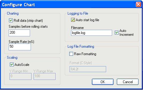
5. To set up the chart, go to Chart | Chart Setup in the menu headings, and the following dialog box will appear.
6. In general, it is useful to select both the Auto Start Log File and the Auto Increment tab. But if you wish to view a running chart without logging data, deselect the Auto Start Log File tab. The Auto Increment feature appends the .log file name with an (#), which increments each time a log is started with the same filename.
7. Type the file name the log is too be saved as in the Logging folder of ECU Files.
8. To disable the autoscale feature and specify the y-axis scale, uncheck the AutoScale button.
9. Raw Formatting records enumerated values by their integral value, and not their text equivalent. In addition, units will not be recorded with the variable values. To plot .log files using Excel or Matlab, check the RawFormatting box.
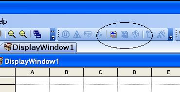
10. With Display connected and the window active, use Chart | Open Chart from the menu headings to start a chart/log. Or use the buttons illustrated below. These buttons will be highlights when Display is on-line.
Display Sheets and Pages
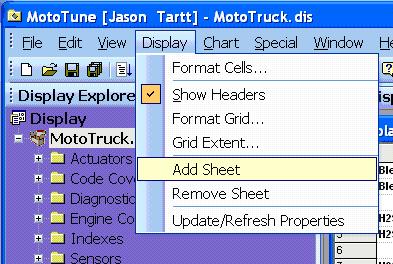
1. To add a sheet to an existing Display Page, go to the Display menu heading and select Add Sheet.
2. The sheet name defaults to Sheet1 – to rename the sheet, double click on the name and type in the new desired name.
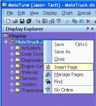
3. A Display Page may have multiple sheets, but only one sheet may be active at a time, and therefore only one chart from that Display Page may be active at a time. To have multiple charts open, add a second Display Page by right-clicking on the Display name and selecting Insert Page.
4. Step through the Set-up Wizard to create the page.
5. To turn pages on and off from the screen, use the Manage Pages feature shown in the image above and check the Page you would like to show or remove.
Display Warning Limits
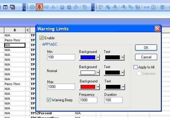
1. In the Display page, variables can be configured to change color or sound when the value exceeds a configured limit.
2. The Warning Limits configuration page can be accessed by wither right clicking on the display variable value, or by going to Tool Bar button shown in the above figure.
3. To set up this feature, select the enable button and configure the cell color and text color to be used when the value exceeds the min/max threshold.
4. If the Warning Beep is enabled, the computer will beep at the selected Frequency and Duration when either the min or max threshold is exceeded.
5. Warning Limits can either be configured on a per cell basis, or for the entire page by selecting the Apply to All button.
Reprogramming Using Boot Key
When working in the prototype phase with newly created .srz files from MotoHawk, it possible to program an .srz with errors in the CAN software or in the model that prevent communications with the module once programmed. When this happens, the module appears to be locked up or frozen when accessing the module via MotoTune. In this case, use the Boot Key to force the module into reboot mode such that a known, valid .srz can be reprogrammed into the module.
The Boot Key has a 10 pin CAN connector that should be inserted into an open port on the CAN junction box. The device generates a 555 Hz, 5V signal out of pin E when power is applied to pin A and ground applied to pin B. When this signal is received on the appropriate pin of the module, it is forced into reboot mode and will allow the module to be reprogrammed.
1. Plug the Boot Key into the junction box and make sure that power and ground are connected to pins A and B on the junction box. Connect pin E of the junction box to the channel listed below on the following modules.
- ECM48_555 – ESTOP
- PCM80_555 – ESTOP
- PCM128_563 – DG1
- HCM48_563 - STOP
- ECM48_563 – N/A
- To boot strap the ECM48_563 module, connector the following channels and follow the steps below.
- AN1 – AN6 Pull to +5V
- AN8 Pull to GND
- AN11 & AN12 Pull to +5V
- AN1 – AN6 Pull to +5V
- To boot strap the ECM48_563 module, connector the following channels and follow the steps below.
- 24 Pin S12 modules
- Read the following: HCS12 Boot Cable
2. With the power to the module off and the boot key installed, select a known, valid .srz file to flash onto the module and program the module.
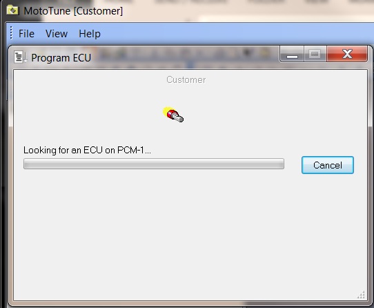
3. When the “Looking for an ECU” prompt appears in the dialogue box, turn on power to the ECU. The module must “wake-up” with the boot key applied in order to force a reboot.
Changing City ID
The basic steps to creating a MotoServer Port with a different CityID are outlined below.
1. In order to communicate with modules with different City IDs, you must first configure a port in MotoTune dedicated to that CAN City ID.
2. From the MotoServer icon in the lower right hand corner of the computer, right click on the icon and open up the Ports configuration window.
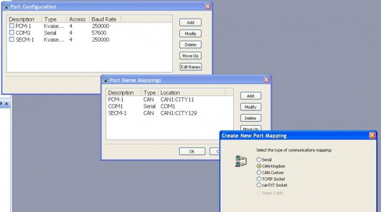
3. Select Edit Name, select Add, select CAN kingdom, and select Next.
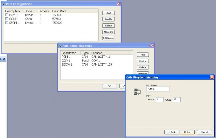
4. In the new window, rename the port to something descriptive (PCM-2 or PCM-B) and set the City ID to the desired ID in Decimal.
- Hex 0xA == Decimal 10
- Hex 0xB == Decimal 11
- Hex 0xC == Decimal 12
- Hex 0x81 == Decimal 129
- Hex 0xA == Decimal 10
5. Select Finish, then OK to exit the Port Name Mappings window. This step has created the port. Now, the port needs to be Added to the Port Configuration Window.
6. In the Port Configuration Window, Select Add
7. Select the Type of Port (ex. Kvaser CAN), and the Location you have just created. Set the Access Level to 4, and select the desired baud rate. Click OK.
Changing the Connection Baud Rate
While MotoTune connections default to 250k Baud for CAN (as does all MotoHawk CAN Blocks, including the MotoTune handler), in some situations it is desirable to change this speed. In order to modify the settings, you should right click on the MotoServer icon in your system tray and select 'Ports...', (see below)
Then, select your port by clicking on its name in the list (usually, this will be 'PCM-1'). Then hit the 'Modify' button.
You will be presented with the configuration for your selected port, here you may update the baud rate.
Setting DLL file locations
To add a folder to MotoServer's dll search list.
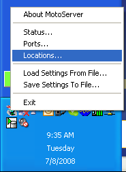
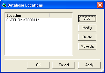
Right click on MotoServer in the system tray and select locations.
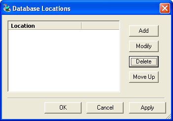
Click Add to add a location or select an existing location and click Modify.
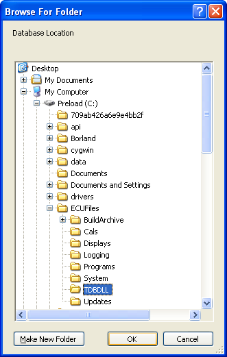
Select the folder. The default location is C:\ECUFiles\TDBDLL
The new location will now be in the list of locations.
Capturing a Communications Debug Log
To capture a communication debug log, right click on the MotoServer icon and choose port.
In the Port Configuration window, chose the desired port and click the modify button.
In the Port Properties window, click the More Info button.
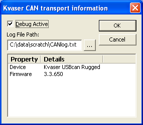
In the Kvaser CAN transport information window, check Debug Active and choose a log file location.
For each connection to MotoTune on a given port, a new log file will be created in the chosen location. The file name will be incremented each time, for example CANlog(0).txt, CANlog(1).txt, etc.
