 |
|
|
The 60 minus 6 encoder pattern has 60 teeth distributed equidistantly about a rotating target of which 6 specific teeth have been removed. The figure illustrates the pattern when used as a 2-stroke.
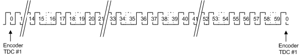
The distribution of missing teeth about the target allows each detected missing tooth to act as a synchronization point. The crank encoder will synchronize from a stall condition upon observing two missing teeth. Each detected missing tooth after initial synchronization allows resynchronization to occur. A crank synchronization error results if the tracked crank angle position does not equate to the absolute position inferred at the resynchronization point.
A resynchronization can temporarily impact the behavior of crank-synchronous blocks. Impacts include a pulse not scheduling as expected, having it occur twice, or being malformed. The system will recover, but the initial impact is unavoidable because the correction to the crank angle position results in a step change in position that may disrupt the underlying pulse scheduling software.
Neither edge of the halfmoon cam should fall within a missing tooth region for all engine operating conditions. Unreliable crank encoder synchronization may occur (which will lead to encoder errors) if an edge transition were to occur within this region.
A cam error will be reported if the width does not conform to the following:
The need for pulse width information precludes the use of a variable reluctance type sensor on the cam. Furthermore the halfmoon cam arrangement assumes that a zero speed sensor is in place. Such a sensor is able to reliably report the presence or absence of metal with minimal to no rotation so that cam state information is always available when a missing tooth is detected (which drives synchronization and re-synchronization activities).
The cam delay attribute defines the phase relationship between the crank and cam encoder. The value is specified as a number of crank angle degrees from a referemce cam position ("ideal"). It is calculated by noting the number of teeth between the rising edge of the "ideal" cam signal relative to where the actual rising edge occurs. The figure below illustrates the "ideal" cam position along with some example cam delay values.
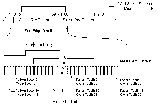
The illustrated cam delay is 18degCA because there are 3 teeth (each representing 6degCA) between the actual cam signal and the "ideal" cam signal. If the cam had been 3 teeth after the "ideal" cam then the CamDelay would have been 720degCA minus 18degCA (=702degCA). There is margin for error provided the cam edges are not located near the missing teeth. A cam delay of 24degCA would also work for the illustrated example. Best operation with the widest tolerances is achieved by aligning the cam edge to bisect the region between two synchronization points (missing teeth).
| Copyright 2009 Woodward Corporation. All Rights Reserved. | Visit Us: mcs.woodward.com |