 |
|
|
The GM24Xe encoder pattern is a pulse width based encoder that consists of 24 teeth. The teeth are characterized as being either wide or narrow. The teeth are displaced about the target and arranged such that one edge of each tooth is equidistantly displaced about the rotating target.
Synchronization on GM24Xe is achieved by encoding unique patterns within the teeth by using a combination of wide or narrow teeth. Crank angle information is communicated by way of the synchronous edge and absolute position can be calculated each time one of the unique patterns is observed. The conclusion of each pattern is referred to as a synchronization point.
A half moon cam encoder can be used to provide engine half cycle information in a 4-stroke system. The state of the cam is interrogated each time a synchronization point is observed so as to determine the current half cycle. Variable reluctance type sensors are not suitable because state information is required at the various synchronization points. The implementation also assumes a zero speed like sensor. Such a sensor is able to reliably report the presence or absence of metal with minimal to no rotation so that cam state information is always available when a synchronization point is detected.
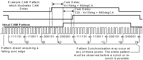
The cam delay attribute defines the phase relationship between the crank and cam encoder. The value is specified as a number of crank angle degrees from a referemce cam position ("ideal"). It is calculated by noting the number of teeth between the rising edge of the "ideal" cam signal relative to where the actual rising edge occurs. The figure below illustrates the "ideal" cam position along with some example cam delay values.
The illustrated cam delay is 60degCA because there are 4 teeth (each representing 15degCA) between the actual cam signal and the "ideal" cam signal. If the cam had been 4 teeth after the "ideal" cam then the CamDelay would have been 720degCA minus 60degCA (=660degCA). There is margin for error provided the cam edges are not located near the synchronization points. A cam delay of 75degCA would also work for the illustrated example. Best operation with the widest tolerances is achieved by aligning the cam edge to bisect the region between two synchronization points.
Neither edge of the halfmoon cam should fall within 7.5degCA of a synchronization point for all engine operating conditions. Unreliable crank encoder synchronization may occur (which will lead to encoder errors) if an edge transition were to occur within this region.
A cam error will be reported if the width does not conform to the following:
| Copyright 2009 Woodward Corporation. All Rights Reserved. | Visit Us: mcs.woodward.com |