
SPI Device Definition
This MotoHawk™ block defines an instance of a Generic SPI Device.
Block ID
GenericSPIDeviceDefn
Library
motohawk_GenericSPI_lib
MotoHawk_lib/Device Specific/SPI Device Blocks
Description
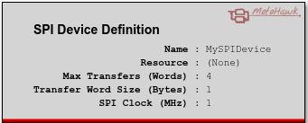
This block is used to define and name an instance of a generic SPI Device. Select an SPI resource and provide a name that accessor blocks will use to reference this instance.
Only a target module that exposes an SPI Device as a generic device will have selectable resources. A target module may incorporate many SPI Devices that are not exposed to this blockset. Typically such devices have been abstracted via dedicated block sets like the MLX90363
Accessor and utility blocks are:
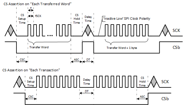
Note that the timing annotations are generalized. The underlying ControlCore driver can be influenced by what can be achieved by the SPI silicon of the microcontroller.
Block Parameters
| Parameter Field | Values | Comments/Description |
|---|---|---|
| Name | Alpha-numeric text, single-quote enclosed | Name of the device. Should be unique and C-legal (no special characters such as spaces, dashes or commas, but underscore allowed). Accessor blocks will reference this name in order to associate an access with this device instance. |
| Resource | Drop-down list | Lists supported resources; options are dependent upon the selected resource. |
| Max number of Transfers (Words) | Positive non-zero Integer | Defines the maximum number of transfers in words that the SPI device is expected to support. Can be used by the underlying driver to size supporting resources that might be needed to support SPI transactions. Defines the boundary condition that an SPI Transaction will test against. |
| Transfer Word Size (Bytes) | Drop-down list |
Defines the word size of transfers used by this device in bytes.
A 1 byte word size implies an 8-bit SPI data transfer, a 2 byte word size implies a 16-bit SPI data transfer and so forth. This attribute might be hidden. When hidden the selected Resource has predefined the value of this attribute and deemed that it is not to be altered by the application. |
| CS Assertion on | Drop-down list |
Defines the behavior of the Chip Select (CS) during the SPI transaction. Each Transferred Word specifies that the Chip Select signal will de-assert between each transferred word. Each Transaction specifies that the Chip Select signal will remain asserted for the entire transaction. This attribute might be hidden. When hidden the selected Resource has predefined the value of this attribute and deemed that it is not to be altered by the application. |
| SPI Clock Frequency (MHz) | Positive numeric |
Defines the desired transfer baud rate. The SPI SCLK signal will not be faster than this value. Certain values may lead to warnings or errors if the selected Resource has advisory values associated with it. This attribute might be hidden. When hidden the selected Resource has predefined the value of this attribute and deemed that it is not to be altered by the application. |
| SPI Clock Phase | Drop-down list |
Defines how the slave device behaves with respect to the SPI Clock (SCLK) signal. Capture on Leading Send on Trailing specifies that the device will use the leading SCLK edge to clock in data sent by the master and clock out data on the trailing SCLK edge. Send on Leading Capture on Trailing specifies that the device will clock out data on the leading SCLK edge and clock in data sent by the master on the trailing SCLK edge. This attribute might be hidden. When hidden the selected Resource has predefined the value of this attribute and deemed that it is not to be altered by the application. |
| SPI Clock Polarity | Drop-down list |
Defines how the SCLK signal idles. Inactive Low specifies that the SCLK signal will start out at logic-0 when CS asserts and the first edge will be a rising edge. Inactive High specifies that the SCLK signal will start out at logic-1 when CS asserts and the first edge will be a falling edge. This attribute might be hidden. When hidden the selected Resource has predefined the value of this attribute and deemed that it is not to be altered by the application. |
| Transfer Delay (ns) | Positive integer |
Defines the desired Transfer Delay, which is typically the delay between CS assertions.
An SPI driver that is able to control this attribute will ensure that at least the specified delay is delivered. Certain values may lead to warnings or errors if the selected Resource has advisory values associated with it. This attribute might be hidden. When hidden the selected Resource has predefined the value of this attribute and deemed that it is not to be altered by the application or the underlying driver is not able to control this attribute. |
| CS Setup Time (ns) | Positive integer |
Defines the desired CS Setup Time, which is typically the delay between CS assertion and the first SCLK edge.
An SPI driver that is able to control this attribute will ensure that at least the specified delay is delivered. Certain values may lead to warnings or errors if the selected Resource has advisory values associated with it. This attribute might be hidden. When hidden the selected Resource has predefined the value of this attribute and deemed that it is not to be altered by the application or the underlying driver is not able to control this attribute. |
| CS Hold Time (ns) | Positive integer |
Defines the desired CS Hold Time, which is typically the delay between the last SCLK edge CS de-assertion.
An SPI driver that is able to control this attribute will ensure that at least the specified delay is delivered. Certain values may lead to warnings or errors if the selected Resource has advisory values associated with it. This attribute might be hidden. When hidden the selected Resource has predefined the value of this attribute and deemed that it is not to be altered by the application or the underlying driver is not able to control this attribute. |