
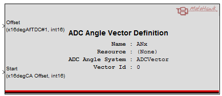
ADC Angle Vector Definition
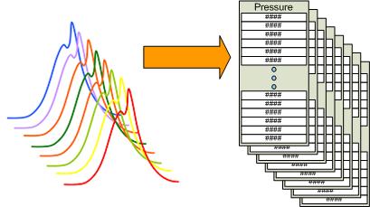
This MotoHawk™ block is used to associate an ADC input to one of the vectors generated by the ADC Angle Vector System Definition block as well as to define the sampling window. This would correspond to one of the grey blocks in the figure below.
Block ID
ADC Angle Vector Definition
Library
MotoHawk_lib/Analog I/O Blocks
Description
Overview
The ADC Angle Vector behavior allows multiple ADC channels to be sampled. This block associates an ADC input resource to an ADC Angle Vector System Definition.
The data maintained by this element may be retrieved via the ADC Angle Vector Get block.
Crank Angle Window Control
Each sample element is directly associated to a specific position in the crank angle domain. It is based upon the value of the "Offset" signal. Consider that the system has an interpolative spacing of 1 degree of crank angle (degCA) and is a 4-stroke, which means there are 720 elements in an instance of a vector. If the "Offset" was zero then element #0 of the vector would correspond to 0 degAfTDC#1 and element #1 would be 1 degAfTDC#1. However, if the offset was 270 degAfTDC#1 then element #0 would be 270degAfTDC#1 and element #1 would be 271 degAfTDC#1. For example, setting "Offset" to 180 in a system that fired 1, 2, 3, 4 would associate this element with cylinder #2. Element #0 of the vector would correspond to TDC#2.
The "Start" signal defines where the complete trigger will occur relative to the offset. Consider that the "Offset" is zero and that the system setup is the same as has been previously described above. If "Start" was 10 then element #0 will be newer in time than element#10. This is because the vector will be filled as follows 10, 11, 12 ... 719, 0, 1, ... 9. The "Start" locates where the trigger will execute.
Enable Port
The optional enable input port allows execution bandwidth to be saved when a vector is not required. The port could be used to disable a vector that corresponds to a cylinder that is not being used (say because the model is designed to support multiple cylinder configurations) or to disable a vector while certain runtime conditions exist. The Ready trigger will not occur for a vector that is disabled. Some underlying device driver activity is also stalled for a disabled vector (which will save further CPU bandwidth).
All defined vectors are considered enabled if the enable port option is not used or the port is left unconnected.
Block Parameters
| Parameter Field | Values | Comments/Description |
|---|---|---|
| Name | 'single-quote' enclosed alpha-numeric text | No special characters such as spaces, dashes, commas (underscore allowed). Select a unqiue name. This name shall be used within the ADC Angle Vector System Definition to reference this element. |
| Resource | Drop-down list | Select appropriate resource. |
| ADC Angle Vector Definition System Name | 'single-quote' enclosed alpha-numeric text | Set to the name of the ADC Angle Vector System Definition block that this element applies to. This allows this block to reference the appropriate ADC Angle Vector Object Definition block. |
| Vector ID | Numeric (Integer) | Zero-based element order. Use the value of 0 (zero) if this definition applied to 'Cyl1' in a system that defined two vectors 'Cyl1 Cyl2' within the ADC Angle Vector System Definition. If it was 'Cyl2' then the value of 1 (one) would be used. This is also the value that will appear at the Vector ID output of the ADC Angle Vector Get block. |
| Use Enable Port | Check box | Check this box to expose the enable input port that will allow the application to define when Ready triggers for this vector should be generated. It is discussed further in the text above for Enable Port. |