
ADC Angle Vector System Definition
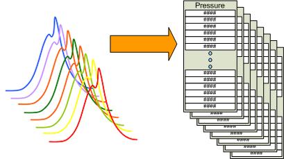
This MotoHawk™ block is used to define an system that can capture multiple channels of crank angle synchronised data from an ADC. Related blocks like the ADC Angle Vector Get block can then be used to export the captured data as a series of vectors. This block, when combined with a number of ADC Angle Vector Definition blocks can be used to capture in-cylinder pressure data for a number of engine cylinders
Block ID
ADC Angle Vector System Definition
Library
MotoHawk_lib/Analog I/O Blocks
Description
Overview
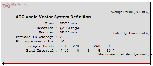
The ADC Angle Vector blocks use an internal interpolative encoder edge output to generate a trigger signal for the ADC. The "Average Period" output details what the last encoder period was in microseconds. The interpolative encoder uses this average period, along with the "Elements in Vector" attribute, to calculate what the interpolation spacing between ADC trigger edges will be.
Under periods of rapid acceleration it is possible for the sum of the interpolation times to exceed the available encoder tooth period. Those edges that don't fit within the actual encoder tooth period are considered late. They are not missed, but instead are squashed together. The "Late Edge Count" output exports the total number of trigger edges that had to be squashed into the observed period. The "Max Consecutive Late Edges" output port exports the maximum number of consecutive edges that were squashed together. The consecutive late edge count would be 2 if 12 trigger edges were supposed to have occurred in one encoder tooth period, but because of acceleration, only 10 could occur. These attributes provide feedback on whether the interpolation is suffering from too many errors
* NOTE: The execution triggers that can be associated to this definition object will execute in a Task context. This is why there are tasking configurations available.
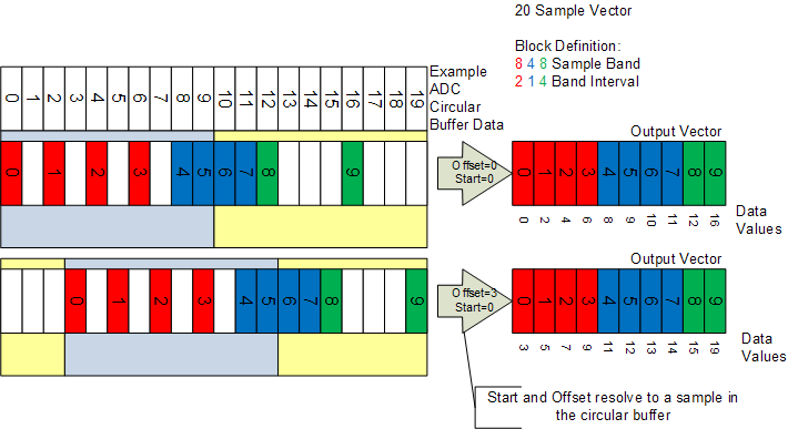
Sampling Bands
Sampling bands allow the application to define what data is to be exported to an output vector and what data should be discarded. No data is discarded if sampling bands are disabled by not checking the Use Sample Bands check box. In effect not using the sampling bands equates to defining a single sampling band that describes the entire cycle.
Sampling bands give the application the ability to conserve memory by only keeping data that is of use. For instance, an application that samples a combustion pressure trace is predominately only interested in the portion of the trace where the combustion occurs. Sampling bands allows such a trace to be broken down into different bands or regions that will export the data based upon an interval that has been defined for the band.
The trace illustrates a simple system. The ADC is sampled 20 times in a cycle, but the exported vector has only 10 elements because the Sampling bands and Band Interval result in some of the data being discarded. Here the data in the middle of the vector is considered important and so a Band Interval of 1 is used to ensure that none of that data is discarded. The data at the end of the vector is less important and so a Band Interval of 4 is used which results in 3 of every 4 samples being discarded.
Limitation - Periods in Average
There are some situations and system architectures where the ADC Angle Vector System will not function. For instance ADC Angle Vector will not function when it is required to use a single tooth encoder as its primary source. As an example, this might occur when a single tooth cam is in use with a 60 tooth crank source that has been diagnosed as being in fault. The system switches to using the cam in order to support a "limphome" function. The ADC Angle Vector System will not function while the single tooth cam is the active encoder source.
In more general terms, the Periods in Average must be fewer than the number of teeth in an engine cycle.
There isn't a direct feedback available to indicate when the ADC Angle Vector System is not able to function, but it can be inferred. It can be inferred that the ADC Angle System is not operational if the encoder source reports that it is synchronized and is reporting a non-zero engine speed, but the definition block's average period output reports zero.
Limitation - Vector Size
The ADC Angle Vector behavior expects that the size of the vector (implied by Number of Elements in Vector) will always be larger than the number of encoder teeth in the pattern that is providing crank angle. Improper operation may result if this condition is not met.
Block Parameters
| Parameter Field | Values | Comments/Description |
|---|---|---|
| Name | 'single-quote' enclosed alpha-numeric text | No special characters such as spaces, dashes, commas (underscore allowed). Select a unique name. This name shall be used by related blocks to reference this definition. |
| Resource | Drop-down list | Select appropriate resource. |
| Periods in Average | Numeric (Integer) | The average period used to calculate the interpolated time between trigger edges uses a FIFO with a depth of this value. The latest observed encoder tooth period is inserted into the FIFO |
| Use Sample Bands | Check box | Defines whether the captured vectors will contain bands of samples with different sampling intervals or will map one-to-one with the number of data points that will exist in one cycle. The Number of Elements in Vector attribute will be visible when this check box is not checked and not visible otherwise. The Sample Band Definition and Band Interval attributes will be visible when this check box is checked and won;t be visible otherwise. |
| Sample Band Definition | Integer array |
Each array entry represents a band of samples over which the corresponding Band Interval will apply. The sum
of the bands defines how many data points will exist in one cycle. A sample band of [270 180 270] would result in 720 data points in one cycle. The cycle angle multiplied by 16 must be a multiple of the number of data points because this will define the internal sample interval that will be used. A value of 720 would be valid in a 2-stroke engine cycle (360 degCA) since 360x16=5760, which is a multiple of 720. However, a system wanting 600 samples would not be legal and an error will result. |
| Band Interval | Integer array |
Each array entry represents the sampling interval that will apply to the corresponding sample band. Only one sample
per interval is exported to the output vector. Thus an interval of 10 would see a sample exported, then the next 9 samples discarded, then the
next sample exported and so on. The interval must be a factor of the corresponding sample band. Thus a sample band value of 60 could have an interval of 10, but not 9, because 10 is a factor of 60 where as 9 is not. The size of the output vector is the sum of the sample band divided by the Band Interval. Thus a sample band definition of [270 180 270] with an Interval Band of [10 1 10] would have 234 elements in the output vector (270/10+180/1+270/10=234). |
| Number of Elements in Vector | Numeric (Integer) |
Defines the number of samples that will exist in a vector. Also defines how many interpolation points will exist in one cycle. The cycle angle multiplied by 16 must be a multiple of the Number of Elements in Vector because this will define the internal sample interval that will be used. A value of 720 would be valid in a 2-stroke engine cycle (360 degCA) since 360x16=5760, which is a multiple of 720. However, a system wanting 600 samples would not be legal and an error will result. |
| Represent vector element as this many ADC bits | Numeric (Integer) | Data is captured right justified. A value of 12 would see possible values of 0 through 4095. If the internal ADC is only 10bits then the value is shifted to the left by 2 to give the impression that there is 12bits of resolution |
| Use Task Reference | Checkbox | Allow the block to reference a private (worker) task specified via Task Definition when checked. |
| Task Name | Single quote enclosed string |
The name of the task that will be used by this ADC Angle Vector System.
When Use Task Reference is checked this task name is a reference to a Task Definition that is configured as a private (worker) task. Using a referenced task definition will allow this behavior to employ a task that has the complete gambit of task configuration options available to it. When not checked this string will be used as the name of the task created by this block. If left empty then a name will be created automatically. |
| Stack Size (bytes) | Numeric (Integer) | Any trigger that executes because of this ADC Angle Vector's definition shall execute in a task context where the task's stack is sized based upon this value. Only visible and applicable when Use Task Reference is not checked. |
| Stack Margin (bytes) | Numeric Value | Provide a margin that could be used by the application monitor. Only visible and applicable when Use Task Reference is not checked. |
| Processing Task Priority | Drop-Down List | Any trigger that executes because of this ADC Angle Vector's definition shall execute in a task context where the task's priority is defined based upon this value. Only visible and applicable when Use Task Reference is not checked. |
| Vector Names | 'single-quote' enclosed, spaced alpha-numeric text | Single spaced names of ADC Angle Vector Definition blocks associated with this definition. If there were two ADC Angle Vector Definition blocks named 'Cyl1' and 'Cyl2' then the appropriate value for this field would be 'Cyl1 Cyl2'. |