
PWM HBridge Output Definition
This MotoHawk™ block is configurable for controlling pulse-width modulation (PWM) output specifically for HBridges.
Block ID
HBridge_Output
Library
MotoHawk_lib/Analog I/O Blocks
Description
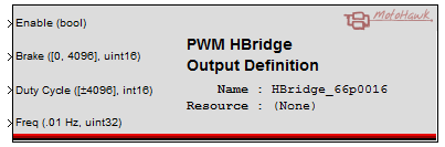
This block includes the Frequency and Duty Cycle (DC) inputs, DC values range int16 -4096 to 4096, where 0 represents 0% and 4096 is 100%. Positive values have the current flow from H(A/+) to H(B/-) negative values will have current flow from H(B/-) to H(A/+). The Frequency input is uint32 which represents 0.01Hz. The percent braking PWMs both legs for the duty cycle and will float rest of the time. This block is largely superseded by the PWM block.
Block Parameters
| Parameter Field | Values | Comments/Description |
|---|---|---|
| Name | Alpha-numeric text, single-quote enclosed | Name exposed to instrumentation. Should be unique and C-legal (no special characters such as spaces, dashes or commas (underscore allowed). |
| Resource | Drop-down list | Select from available resource, per target ECU, such as H-bridge, etc. |
| Input Enable | Check box (enable) | When "Input Enable" is checked, the output may be dynamically controlled. When disabled, the output transistors are completely turned off, which will stop all current. |
| Input Brake | Drop-down list | Select "Off/On" to have a boolean switch for braking, or select "Percent" to PWM the brake at the duty cycle specified at the Brake input. A non-zero value on the Brake input overrides the Duty Cycle input. |
| Use Minimum Frequency | Check box (enable) | Enables the Minimum Frequency (Hz) field. |
| Minimum Frequency (Hz) | Numeric | Setting this value tunes the clocks used for PWM generation and should be set to the minimum expected frequency. The Frequency input is uint32 and each unit represents 0.01Hz. |
| Use Maximum Frequency | Check box (enable) | Enables the Maximum Frequency (Hz) field. |
| Maximum Frequency (Hz) | Numeric | Setting this value tunes the clocks used for PWM generation and should be set to the maximum expected frequency. The Frequency input is uint32 and each unit represents 0.01Hz. |