
PWM Output Definition
This MotoHawk™ block is configurable for controlling pulse-width modulation (PWM) output.
Block ID
motohawk_pwm
Library
MotoHawk_lib/Analog I/O Blocks
Description
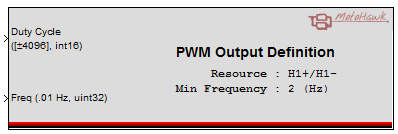
Duty cycle and Frequency
This MotoHawk™ block allows the attributes of pulse-width modulated (PWM) output to be modified. Frequency and dutycycle are the two key attributes. Dutycycle defines the percentage of the period (which is specified by the frequency) that the resource will be turned on (assert). Thus a low side driver output resource will sink current into the driver switch for the percentage of the period specified by the dutycycle. On the other hand, a highside driver output resource would source current for the percentage of the period defined by the dutycycle.
The frequency input signal, which defines the period (1/freq), has units of 0.01Hz and thus a value of 1000 actually represents a commanded frequency of 10Hz.
Dutycycle is signed and ranges from -4096 (-100%) to 4096(100%). A negative value encodes direction and is only applicable when used with a resource like a full H-bridge that is direction capable. Resources that are not direction capable will take the absolute value of the supplied dutycycle and thus will ignore the sign.
Update Rate Considerations
Most PWM outputs will only use the latest commanded dutycycle and frequency when the current excitation period has completed. Thus there is no real value in commanding a PWM operating at 100Hz (T=1/freq=1/100=10ms) at a rate of once every 5ms since every second command is over written with a new command before it has been used by the PWM driver. There is no harm in commanding the output more often than necessary. It just represents a waste of execution bandwidth.
Minimum Frequency
The output capability of the PWM resource is hardware dependent. The underlying hardware typically uses counters to implement a PWM. One counter is used to time the period and the other is used to time how long to assert the output (which is determined from the duty cycle). The counters are clocked by an internal clock and have a finite number of bits. Thus they can only time a finite period that is defined by the clock rate and the range of the counter. This finite period defines the lowest frequency that the driver can attain. MotoHawk™ will clip the commanded frequency to this hardware specific value.
Minimum Frequency can help MotoHawk™ determine what internal clock to use so as to configure itself to achieve the requested frequency range whilst delivering the best possible dutycycle granularity.
For example, consider that an arbitary PWM implementation can support an internal clock of 1MHz or 100kHz and that its counters are 16bits. A 16 bit counter being clocked at 1MHz can generate a minimum frequency of 1MHz/65536 ~ 15Hz. That same PWM when clocked at 100kHz can generate a frequency down to 1.5Hz. Commanding a frequency that is lower than this hardware defined value will be be clipped to this supported value. If the output's minimum frequency was specified at 10Hz then the driver would need to select the 100kHz clock because the 1MHz clock couldn't generate a PWM at a frequency of 10Hz. If the Minimum Frequency was set to 20Hz then the system would know that the 1MHz clock could be used.
The higher the base clock that can be used the better the granularity of the control. A 40Hz control running with a 1MHz clock has 1MHz/40=25000 discrete points of control, which is better than the number of discrete points that can be represented by the duty cycle signal (4096). However, that same control running with a 100kHz clock has 100kHz/40=2500 discrete points of control, which is less than could be represented by the duty cycle signal. Thus the 1MHz clock will provide better control and MotoHawk™ can select this if it knows the application won't need to support a frequency that is below 40Hz. Minimum Frequency allows this decision to be made.
Enable Input
The Enable input allows the condition of the drive to be controlled dynamically. An output that is disabled turns off all of the switches, regardless of the supplied PWM. This will prevent current re-circulation, which will alter how the load behaves. Some hardware is also able to disable its control immediately. Thus some hardware won't wait for the current excitation period to expire before this condition is applied.
See Also
PWM Synchronized Child Definition
Block Parameters
| Parameter Field | Values | Comments/Description |
|---|---|---|
| Name | Alpha-numeric text, single-quote enclosed | User defined Resource name. When using the PWM output as a parent for a synchronized PWM on ComponentControlCore Module Types, it is required to provide a name in this field that matches the parent reference name parameter in a PWM Synchronized Child Definition |
| Resource | Drop-down list | Select from available resource, per target ECU, such as H-bridge, etc. |
| Minimum Frequency(Hz) | Numeric | The Minimum Frequency informs the MotoHawk driver of the lowest frequency that will be requested by the application. This allows MotoHawk™ to select appropriate clock dividers and so forth that allows the driver to deliver the best possible duty cycle and frequency granularity. Whether this attribute is able to affect the output is dependent upon the capability of the driver, which is target specific. |
| Use Maximum Frequency | Check box (enable) | This check box will expose the Maximum Frequency attribute. MotoHawk™ will only consider Maximum Frequency when this check box is checked. |
| Maximum Frequency(Hz) | Numeric | Maximum Frequency informs the MotoHawk™ driver of the highest frequency that will be requested by the application. This allows MotoHawk™ to select appropriate clock dividers and so forth that allows the driver to deliver the best possible duty cycle and frequency granularity. Whether this attribute is able to affect the output is dependent upon the capability of the driver, which is target specific. |
| Input Enable | Check box (enable) | The condition of the output can be dynamically controlled when Input Enable is checked. The output transistors are completely turned off, which will stop all current. |
| Input Brake | Check box (enable) | Only useful in a full H-Bridge configuration. This signal will put the H-Bridge into a brake configuration where current recirculates through the load. Not supported by all ECMs. The level of braking is controlled by the dutycycle input where 0% is no braking, 100% is full braking |
| Output Current | Check box (enable) | When "Output Current" is checked, the drive current in milliamps is provided. Whether the output can provide current is hardware dependent. |
| Output Fault Status | Check box (enable) |
Only visible for supporting modules (Classic Module Types) or when already checked. This option
exposes the optional diagnostic output port on the block when checked. Modules that don't support this option expose dignostic information via blocks
like Detailed Fault Status or IO Fault Status. The fault status of the output is queried when the block executes, which will report one of these values: 0 - OK 1 - Fault 2 - Indeterminate "motohawk_fault_status_enum" is a script that returns a cell array with that enumeration. It can be used in the Enumeration field of a probe to decode the return value of this block. The behavior of the fault status is dependent upon the capability of the underlying hardware. Some hardware may cache observed faults and report them when next queried whilst other hardware may only be able to report the instantaneous fault status. Often Indeterminate is returned when the hardware is unable to determine the fault status of the output when it was queried. For example, some outputs can only detect open circuit while they are asserted and so may report indeterminate while not asserted. |
| Use as parent for synchronized PWM | Check box (enable) | When "Use as parent for synchronized PWM" is checked, a Synchronized Child PWM block may be used to reference this block. |
| Allow I/O pin to be calibrated from Intrumentation Tool | Check box (enable) | Name, Access Levels and Instrumentation Group Strings fields available. This field is only available on Classic modules, see ModuleTypes for help. |
| Calibration Name | Alpha-numeric text, single-quote enclosed | Name as displayed in Instrumentation tool, for block. No special characters, such as spaces, dashes, commas (underscore allowed) |
| Read Access Level | 0-8 | Sets security level 1 lowest, 8 highest, for user access to read value. A setting of zero indicates unsecured access is allowed. |
| Write Access Level | 0-8 | Sets security level 1 lowest, 8 highest, for user access to write value. A setting of zero indicates unsecured access is allowed. |
| Instrumentation Group | Alpha-numeric text, single-quote enclosed | Defines the desired Folder name and hierarchy to be used by suitable Instrumentation Tools. Use "|" character between folder names to delineate subfolder structure. |