
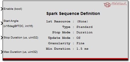
Spark Sequence Definition
This MotoHawk™ block sets up a sequence of spark coil drivers, starting with the given pin and working up, one for each driver required by the 'Sequence Type'.
Block ID
Spark Sequence
Library
MotoHawk_lib/Advanced Digital I/O
Description
The input ports may be scalars or vectors, but if vectors, the size must equal the number of cylinders defined by the Encoder Definition block. This number may be calibratable, in which case the vector must be as large as the 'Maximum Number of Cylinders'. When diagnostic outputs are enabled, open and short circuit detection is made available. The Open and Short outputs are one of: 0 - OK 1 - Fault 2 - Indeterminate
The end of a pulse can create a trigger using the PSP End Trigger Block.
Angle inputs are before TDC (BfTDC), in units of 1/16th of degree crank angle. Time inputs are in microseconds.
Eg: 730degBfTCD == 10degBfTDC == -710degBfTDC
Angles are converted internally to Mod(angle, DegInCycle). It is therefore not possible to schedule a pulse more than one cycle into the future.
When Mod(start - stop,DegInCycle) == 0, angular duration is considered to be zero. For example, this will occur on a 4-stroke when start = 720, stop = 0. To achieve a maximum angle, stop = start - DegInCycle - 1/16.
Block Parameters
| Parameter Field | Values | Comments/Description |
|---|---|---|
| 1st Resource | Drop-down list | Select from available listings, as appropriate, to assign initial pin of sequence. |
| Sequence Type | Select sequence type from list | |
| Standard Coil (Coil per Cylinder) | (per cylinder) | |
| Banked (Fire on both phases until CAM sync) | (per 2 cylinders & half duration) | |
| Batch (wasted spark) | (per 2 cylinders & half duration & all cylinders) | |
| Muxed (distributed) | ||
| Stop Mode | Select method for Stop | |
| Angle Controlled | Control Stop Mode by Angle | |
| Duration Controlled | Control Stop Mode by Time Duration | |
| Update Mode | Select whether to have the OS protect against pulse errors. Only visible for supporting modules (Classic Module Types). Modules that don't support will always use the OS update mode. | |
| OS | ControlCore protects against missing pulses. | |
| Application | No error checking is provided, and the application is completely trusted. Not recommended. | |
| Granularity | Select granularity (resolution) as required. Only visible for supporting modules (Classic Module Types). | |
| Fine | Uses interpolation to schedule angles that fall between encoder teeth. | |
| Coarse | No interpolation, uses encoder teeth to identify engine position. | |
| Minimum Duration Mode | Select whether to have static or dynamic minimum duration. Only visible for supporting modules (Classic Module Types) | |
| Static | Select to have constant value, input in mask | |
| Dynamic | Select to have value calculated in model and input into the block as a signal port. | |
| Minimum Duration (ms) | Numeric | Only visible for supporting modules (Classic Module Types). Any scheduled electrical injector duration smaller than this value is considered to have zero duration when scheduled. Is a member of the mask when the static Minimum Duration Mode is selected and is a signal when dynamic is selected. |
| Output Spark Diagnostics | Check Box (enable) |
Only visible for supporting modules (Classic Module Types) or when already checked. This option
shows the diagnostic output ports on the block. Modules that don't support this option expose dignostic information via blocks like
Detailed Fault Status or IO Fault Status. Open and short circuit detection, when supported, will take on one of these values: 0 - OK 1 - Fault 2 - Indeterminate |
| Open-Circuit Threshold [ADC Counts] | Numeric | Set the numeric threshold for ADC counts. Only visible when Output Spark Diagnostics is checked. |
| Allow I/O pins to be calibrated | Check Box (enable) | Check to enable calibration, and enable below parameters. This field is only available on Classic modules, see ModuleTypes for help. |
| Prefix | Alpha-numeric text, single-quote enclosed | Assigns prefix to name. Use "|" character between folder names to delineate subfolder structure. |
| Read Access Level | 0-8 | Sets security level 1 lowest, 8 highest, for user access to read value. A setting of zero indicates unsecured access is allowed. |
| Write Access Level | 0-8 | Sets security level 1 lowest, 8 highest, for user access to write value. A setting of zero indicates unsecured access is allowed. |
| Instrumentation Group | Alpha-numeric text, single-quote enclosed | Defines the folder name and hierarchy to be used by a suitable instrumentation tool. Use "|" character between folder names to delineate subfolder structure. |