
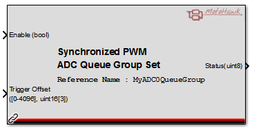
Synchronized PWM ADC Queue Group Set
This MotoHawk™ block allows ADC sample timing attributes to be applied to a Synchronized PWM ADC Queue Group that is synchronized to a Synchronized PWM System Definition.
Block ID
Synchronized PWM ADC Queue Group Set
Library
motohawk_MotorControl_lib
Description
Overview
This MotoHawk™ block allows ADC sample timing attributes to be applied to a Synchronized PWM ADC Queue Group that is synchronized to a Synchronized PWM System Definition.
Input Ports
Enable (bool)
A value of false disables the ADC Queues from sampling. A value of true enables the ADC Queues to be sampled.
Trigger Offset (uint16[])
A vector (one element for each ADC Queue in the Synchronized PWM ADC Queue Group) of fixed point percentage values (4096 represents 100%) that this block is to set. The order that the ADC Queues were defined in the referenced Synchronized PWM ADC Queue Group indicates which vector element affects a particular ADC Queue. The vector values must be in increasing order, and enough time apart to allow the previous ADC Queue to complete
Output Ports
Status (uint8)
The status of the set operation. A value of zero indicates that the set was successful. A non-zero value implies that there was an issue that typically implies that the operation failed. The system is not affected by a failure unless specifically stated otherwise. The m-script motohawk_SyncPWMADCQueueGroup_set_status_enum enumerates the status.
Success (0)
The attributes were successfully applied to the underlying buffers and the hardware will be updated at the next opportunity.
Failure - Queue order (1)
An ADC Queue trigger point was set too close or before the previous ADC Queue. The system was unable to schedule an ADC Queue to be sampled as the prior ADC Queue sampling was not complete.
In order to complete the sampling, the system has delayed the sampling of an ADC Queue until the previous ADC Queue sample has been completed.
Operation
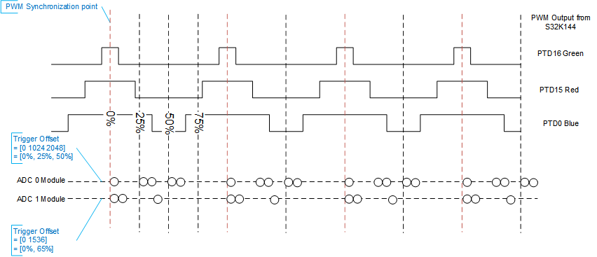
ADC Queues will be triggered to be sampled at the points defined by the input Trigger Offset vector.
For example, with a centre aligned Synchronized PWM, a master trigger is issued at the centre of the PWM duty cycle. A Trigger Offset port vector value of [0, 1024, 2048] would cause the 1st ADCQueue to be triggered at the PWM Synchronization point (middle of duty cycle), the 2nd ADCQueue to be triggered at 25% of the PWM Period, and the 3rd ADC Queue to be triggered at 50% of the PWM Period.
Block Parameters
| Parameter Field | Values | Comments/Description |
|---|---|---|
| Synchronized PWM ADC Queue Group Reference Name | Single quote enclosed alpha-numeric text | The name of the Synchronized PWM ADC Queue Group that this block will set |
| Number of ADC Queues in Group | Integer | Indicates how many ADC Queues this block expects to set. This defines the width of the Trigger Offset input. A Simulink Update error will result if this value does not correlate with the number of ADC Queues that were specified within the referenced Synchronized PWM ADC Queue Group Definition. |