
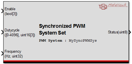
Synchronized PWM System Set
This MotoHawk™ block allows attributes like duty cycle to be applied to the Synchronized PWM Channel Definitions assigned to the referenced Synchronized PWM System Definition in a coherent fashion.
Block ID
Synchronized PWM System Set
Library
motohawk_MotorControl_lib
Description
Overview
This MotoHawk™ block allows attributes like duty cycle to be applied to the Synchronized PWM Channel Definitions assigned to the referenced Synchronized PWM System Definition in a coherent fashion. Coherency is achieved by buffering the supplied attributes and only applying them to the underlying hardware once the current period has expired.
Input Ports
Enable (bool[])
A vector (one element for each PWM channel that is referenced by the PWM system) of enable values that this block is to set. The order that the PWM channels were specified in the referenced system indicates which vector element affects a particular PWM channel.
A value of false disables and a value of true enables. A disabled channel will be turned OFF when the value takes effect, irrespective of the commanded dutycycle. Both halves of a PWM channel that represents a complement pair will be turned OFF for a value of disabled.
Dutycycle (uint16[])
A vector (one element for each PWM channel that is referenced by the PWM system) of fixed point dutycycle values (4096 represents 100%) that this block is to set. The order that the channels were defined in the referenced system indicates which vector element affects a particular PWM channel.
A PWM channel will assert (turn ON) for the percentage of the period specified by the dutycycle value. The high side of a PWM channel that represents a complement pair is affected by the dutycycle value. The low side of the pair will assert while the high side is OFF.
Frequency (uint32)
The frequency of PWM operation in Hertz (Hz). The signal is a scalar since synchronized PWM operation implies that all channels operate at the same frequency.
Output Ports
Status (uint8)
The status of the set operation. A value of zero indicates that the set was successful. A non-zero value implies that there was an issue that typically implies that the operation failed. The system is not affected by a failure unless specifically stated otherwise. The m-script motohawk_SyncPWMSystem_set_status_enum enumerates the status.
Success (0)
The attributes were successfully applied to the underlying buffers and the hardware will be updated at the next opportunity.
Unidentified Failure (1)
The operation did not complete successfully and the system was not affected, but the cause is unknown.
Failure - Not Created (2)
The operation did not complete successfully because the underlying system had not been successfully created. An unexpected resource conflict or bad configuration can lead to
such a failure.
Failure - Pending Update (3)
The Synchronized PWM system was not updated because a previous set operation is still pending.
A set is only applied to the underlying hardware when a new PWM period is about to begin. An attempt to further alter the underlying hardware while the driver is waiting for this condition could lead to an incoherent attribute update. The driver ignores this update request and returns this status rather than allow the possibility of an incoherent update being applied.
H-Bridge Operation
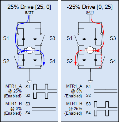
The Synchronized PWM block set aims to abstract the resources to allow for electric machine control (Brushless DC for example), but it can be configured so as to achieve standard H-Bridge control too. Here the signed scalar duty cycle value used by the PWM Output block needs to be converted into a vector of duty cycles using a simple transform. The complementary pairs of each half bridge are then controlled so as to achieve active recirculation when not actively driving in a particular direction.
The transfrom from a signed scalar dutycycle to an unsigned vector of dutycycles could be like so:
IF (sDutycycle >= 0)
Dutycycle[] = [sDutyCycle, 0]
ELSE
Dutycycle[] = [0, 0 - sDutyCycle]
ENDIF
Below are some illustration of this control for a Synchronized PWM System Definition with a MTR1 resource that has two Synchronized PWM Channel Definitions resources named MTR1_A and MTR1_B.
Block Parameters
| Parameter Field | Values | Comments/Description |
|---|---|---|
| Synchronized PWM System Reference Name | Single quote enclosed alpha-numeric text | The name of the Synchronized PWM System Definition that this block will set |
| Number of PWM Channels | Integer | Indicates how many PWM channels this block expects to set. This defines the width of the Enable and Dutycycle inputs. An Simulink Update error will result if this value does not correlate with the number of channels that were specified within the referenced Synchronized PWM System Definition. |