
Knock By Decimation System Definition
Some MotoHawk™ modules utilize a microcontroller that supports silicon assisted decimation filters. The CPU burden to acquire and filter analog data is minimal with such microcontrollers. This block allows an IIR Filter based knock system to be created that will utilizes these decimation filters in its implementation. Associated blocks allow the signal sources to be defined (along with the angle domain window in which they are to sample) as well to specify what sensor is to be used. The main blocks that such a knock system will require to exist is the source definition block, sensor definition block and result accessor block. Multiple instances of these block would exist in the model to allow knock and reference values to be acquired for each cylinder.
Block ID
Knock Decimation System
Library
motohawk_knock_by_decimation_lib
Description
Signals
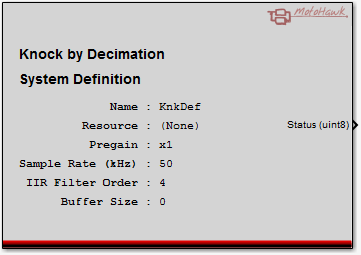
Status Output
The status port reports the health of the knock system. It should be treated as an enumeration with the following definitions
0: OK
The knock system has created successfully and is currently healthy.
1: Error - Insufficient Decimators
The knock system was unable to acquire sufficient decimator modules to support the order of the requested IIR Filter. This error, if it is to occur, typically won't appear until there is engine speed as the filter is not configured until a source becomes active.
2: Error - Sample Rate too High
The knock system did not create because the requested sample rate was too high. A build error may detect this before it gets to this runtime error.
3: Error - No Sources
The knock system did not create because there were no sources specified within the model that utilize it.
4: Error - Internal
An unexpected error was detected within the ControlCore layer that prevented creation.
5: OK - Pending
Preliminary creation was successful, but the coefficients have not yet been applied. Generally this is because there are no active sources, which require engine speed before they can activate. It can also occur if the system does not write any coefficients into the knock system via the Coefficient Set block.
Block Parameters
| Parameter Field | Values | Comments/Description |
|---|---|---|
| Name | Alpha-numeric text, quote enclosed | Name of the Knock by Decimation System that the other blocks will use to reference this definition. This value will be referenced by blocks like the Knock Source defintion. |
| Resource | Drop down list | The list of resources that are capable of supporting this behavior. This is typically driven by the capability of the module's microcontroller. |
| Sample Pre Gain | Drop down list | The ADC has a pre-stage amplifier that can be configured at design time. All conversions meant for this knock system are affected by this setting. |
| Sample Rate (kHz) | Positive number | Defines the rate of analogue to digital conversion. This affects the filter characteristic. The absolute value is dependent upon the capability of the module's ADC. A rate of at least 100kHz should be possible. |
| IIR Filter Order | Drop down list | Defines the order of the IIR Filter that the knock system will utilize. The module will consume internal decimators so as to support the selected filter order. Requesting a filter order that is too high will lead to a runtime creation error that is reported via the block's Status output port. |
| Buffer Size | Zero or Positive integer | This entry defines the size of the buffer of filtered data that will be maintained by the system. This data is accessible via the Knock Data block. If the data is not going to be used then set this value to zero as it consumes system RAM as well as CPU bandwidth to maintain. |
Knock System Architecture
A knock system will basically consist of a single knock system definition block and a series of knock sources, each of which will reference a sensor definition. The same sensor can be used by multiple sources. Each source will utilize a result block to obtain its result. This will likely exist (though it can be asynchronously accessed) within a trigger that fires each time a new result is available. There will also be at least one coefficient set block within the model that will initially configure the knock system. This block could also be used to alter the filter characteristics of the knock system at runtime.
The example model supplied with the block set illustrates this basic setup.
The filters are always running, but their output is only integrated when commanded. Thus the filter will have time to stablise when different sources utilize different sensors..