 |
|
|
The N teeth with X missing encoder style describes those encoder patterns that consist of N equidistant teeth distributed about a wheel with X adjacent teeth then removed. The most common form of this pattern is the "N minus 1" and "N minus 2" patterns. The 60 minus 2, sometimes known as 58X is a member of this encoder style as is 36 minus 1.
The missing teeth are used to communicate synchronization information. Speaking generally, a single missing tooth is detected if a synchronous crank encoder edge is not detected within 1.5 times the previously observed tooth period. If there were two missing teeth then the multiplicand is 2.5 times the previous period.
A crank synchronization error will be flagged if the correct number of missing teeth have been observed without having observed the correct number of real teeth. Thus the 60 minus 2 pattern would issue a synchronization error if two missing teeth were observed without having previously observed 58 physical teeth.
A resynchronization can temporarily impact the behavior of crank-synchronous blocks. Impacts include a pulse not scheduling as expected, having it occur twice, or being malformed. The system will recover, but the initial impact is unavoidable because the correction to the crank angle position results in a step change in position that may disrupt the underlying pulse scheduling software.
The Tooth Cam and the Halfmoon Cam are both considered to be of tooth cam style. Neither edge of the halfmoon cam nor the synchronous edge of the tooth cam should fall within the missing tooth region for all engine operating conditions. Unreliable crank encoder synchronization may occur (which will lead to encoder errors) if an edge transition were to occur within this region.

The width of a half moon cam should approximate 360 crank angle degrees. That is, a cam edge should be observed approximately every 360 crank angle degrees. The tolerance will vary depending upon the number of teeth in the system. For a 60 tooth crank encoder, consecutive cam edges shall be:
Utilizing a Tooth Cam configuration in place of the halfmoon will still allow a fully featured crank-synchronous model to be developed. Therefore a Tooth Cam can be used in place of a halfmoon cam if there is an issue with the width. Cam errors will be reported if a halfmoon is in use that does not conform to the width restrictions.
The halfmoon cam arrangement assumes that a zero speed sensor is in place. Such a sensor is able to reliably report the presence or absence of metal with minimal to no rotation. A halfmoon should be treated as a tooth cam if such a sensor is not available.
The crank teeth from cam edge to crank tooth zero setting is used to assist ControlCore in making an informed guess as to what the half cycle state is when it first observes missing teeth. Correctly setting this value will improve start quality. The setting is ignored when it has a value of -1. Instead ControlCore determines an appropriate value that won't be optimal. A positive value implies that the setting is to be used and communicates to ControlCore the number of crank encoder teeth that need to be observed from speed zero before the system can categorically conclude whether the cam edge would have been observed if it was going to occur prior to the observed missing teeth.
The figure illustrates a setting of 3 teeth. If at least 3 teeth had been observed before the first missing tooth is observed (from speed zero) and a cam tooth has not been observed then the system knows that the detected missing tooth corresponds to the half-cycle that does not have the cam tooth. The system can't make that assumption if 2 or fewer teeth had been observed before the first missing tooth.

The duramax cam consists of three pulses distributed about two engine revolutions. ControlCore uses the narrow pulse widths depicted by the figure as half-cycle markers. The width of these pulses are defined as the number of teeth in an engine revolution divided by 8. Thus for a 60 tooth crank encoder the narrow width could be no wider than 7 crank encoder teeth.

The cam may have any alignment with the crank encoder provided the edge that completes the narrow width does not fall within the missing tooth region and that exactly one narrow width resides in each half-cycle.
Count the number of teeth from the start of the narrow width until the missing tooth region to calculate the Crank Teeth from Cam Edge to Crank Tooth Zero setting.
The cam uses pulse width to determine the half-cycle marker and as such must utilize a sensing technology that will accurately convey pulsewidth information. Thus this cam pattern does not support variable reluctance (VR) sensing.
The coyote cam consists of 8 pulses of varying widths. ControlCore looks for a sequence of widths in order to provide half-cycle synchronization information to the crank encoder.

Cam alignment is restricted to the range dipicted in the figure. Set the Cam Sync Polarity to match the figure.
The cam uses pulse width to determine the half-cycle marker and as such must utilize a sensing technology that will accurately convey pulsewidth information. Thus this cam pattern does not support variable reluctance (VR) sensing.
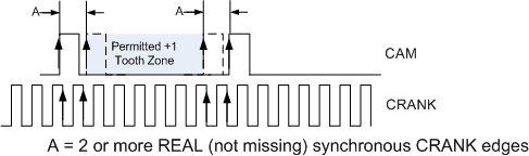
The X+1 CAM compares the widths between CAM teeth to detect a narrow width + 1 pulse advanced or retarded within normal CAM teeth. The presence or absence of the +1 CAM tooth provides half-cycle synchronization information to the crank encoder. Normal CAM teeth are the equally spaced teeth. The +1 tooth occurs once per cycle within the same normal tooth pair.

If the CAM sync point is on or can move either side of the CRANK sync then encoder errors will occur, and TDC will move by 360degrees.
1.- There must be at least two REAL (not missing) CRANK synchronous edges between any two CAM pulses. 2.- There must be less than or equal 32 (REAL OR missing) CRANK synchronous edges between any two CAM pulses.
Encoders with 1 or 2 missing teeth: The CRANK Sync point is located between the last missing tooth and the next real tooth.
Encoders with 3 or 4 missing teeth: The CRANK Sync point is located on the 1st real tooth after the missing.
The 36 plus 1 cam is a specialized variant of the X+1 that exist to circumvent the crank teeth between cam teeth limitation that the MPC5xx implementation must contend with. This pattern identifies the plus 1 tooth of the cam by looking for consecutive instances of a single crank tooth being observed between cam teeth. This will only be observed near the cam's plus 1 tooth when a 36 tooth crank encoder is in use. Thus this pattern is only intended for use with a 36 tooth crank encoder. The standard X+1 could be used otherwise. The presence or absence of the +1 CAM tooth provides half-cycle synchronization information to the crank encoder.

The detection scheme assumes that the plus 1 tooth or the cam teeth either side of the plus 1 tooth will not occur in the missing tooth region. The cam will not correctly synchronize unless this alignment condition is met.
The cam should maintain a tight phase relationship with the crank. Having cam teeth cross crank teeth boundaries during running could lead to synchronization problems and/or encoder errors. If the cam and the crank happen to be aligned then set the crank cam alignment attribute in the encoder definition.
| Copyright 2010-2013 Woodward Corporation. All Rights Reserved. | Visit Us: mcs.woodward.com |