 |
|
|
This block creates an instance of an OBD Fault Definition for use within the OBD Fault Manager environment.
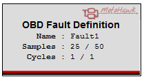
OBD Fault Definition
MotoHawk OBD Fault Manager
This block creates an instance of an OBD Fault Definition for use within the OBD Fault Manager environment.
It can emulate OBD Fault Set block functionality when the input ports are enabled. An automatically created ECU parameter called FaultTest_<FaultName> will be available at runtime which can be used to force the fault to be considered suspected, even if the logic that drives the input port to this block is not active. This can be used to test the failure of the fault and the connected fault actions without satisfying the enable conditions for the fault in the application.
Counters allow a suspected fault to be confirmed if it is present for a specified X samples / Y samples.
| Parameter Field | Values | Comments/Description |
|---|---|---|
| Fault Name | Single quote enclosed alpha numeric | Must be unique and provides the name for calibration entries and allows the fault definition to be referenced from other blocks such as the OBD Fault Set block. This is the name of the new fault. |
| Fault Type (1) | Drop Down | Specifies the default type of the fault. If the fault is configured as "Emissions-Related" then the MIL Request condition can be activated. Also any "Emission-Related" behavior will apply to this fault. This option can be calibrated at run time if the "Add Fault Type Calibration" parameter is checked. |
| Permanent (2) | Drop Down | Specifies the permanent status of the fault. If the fault is configured as "Permanent" then the Permanent condition, when set, won't be cleared unless the Mark To Clear block is used to clear it. The Permanent condition is not impacted if "Not Permanent" is selected. This option can be calibrated at run time if the "Add Permanent Calibration" parameter is checked. |
| Show Suspected Fault Input | Checkbox | Allows the user to use this block as a OBD Fault Set block as well as a definition block. When checked an input port 's' (boolean) is shown on the block. The user can then set the suspected condition of a fault on each execution pass, and the X/Y count will be updated appropriately. This input can be gated by the 'inhibit' input when enabled. The "Show Inhibit Input" checkbox below becomes active when the "Show Suspected Fault" is checked. |
| Show Inhibit Input | Checkbox | If checked, an 'inhibit' (boolean) input port is shown on the block. This allows user to conditionally prevent the block from updating the X/Y counts. |
| Use Sample X/Y Counters | Checkbox | Faulty Samples(X) and Total Samples (Y) can be set when checked and the values are also exposed in calibration. Fault detection is treated as boolean when not checked and the counters are not available in the calibration. This is functionally equivalent to setting Faulty Samples(X) and Total Samples (Y) to 1. |
| Faulty Samples (X) | Edit, unsigned integer | This specifies the number of fault samples that need to occur before the "Total Samples" are exceeded and a fault to be considered "Pending". Gain and Offset are applied to these raw values. |
| Total Samples (Y) | Edit, unsigned integer | This specifies the total number of samples that need to occur before the sampling cycle resets. Gain and Offset are applied to these raw values. |
| Use Drive Cycle X/Y Counters | Checkbox | The Drive Cycle logic used to confirm a fault is enabled when checked. Pending Drive Cycles(X) and Total Drive Cycles (Y) can be set and are available in calibration. When unchecked the Drive Cycle logic is disabled, which means a "Pending" fault immediately becomes "Confirmed". The values of the counters cannot be set and are not available in calibration. This is functionally equivalent to enabling the Drive Cycle logic and setting Pending Drive Cycles(X) and Total Drive Cycles (Y) to 0. |
| Pending Drive Cycles | Edit, unsigned integer | This specifies the number of drive cycles out of "Total Drive Cycles" before a fault is considered "Confirmed". Gain and Offset are applied to these raw values. |
| Total Drive Cycles | Edit, unsigned integer | This specifies the total number of driving cycles that faults must encounter to leave the pending condition. Gain and Offset are applied to these raw values. |
| (1) Add Fault Type to Calibration | Checkbox | If checked, the block will add a calibration for the fault type . |
| (2) Add Permanent to Calibration | Checkbox | If checked, the block will add a calibration for the permanent status . |
| Calibration Name Format | Drop Down | This allows the format of the calibration variable names to be configured. Prefix Name uses <FaultName><AttributeText> Eg: Fault1SuspectedXLimit whereas Postfix Name uses <AttributeText><FaultName> Eg: SuspectedXLimitFault1. Separately available in mask tabs are individual settings for variables, where the calibration AttributeText, Gain, Offset, Units and Help text can be set. |
| Read Level | 0-8 | Sets security level (1 lowest, 8 highest) for instrumentation read access. A setting of zero indicates unsecured access is allowed. |
| Write Level | 0-8 or (Read Only) | Sets security level (1 lowest, 8 highest) for instrumentation write access. A setting of zero indicates unsecured access is allowed. Read only prevents write access. |
| Fault Group | String | Specifies the location of the fault calibrations |
Each of these tabs refers to a counter value on the 'Settings' tab described earlier. The values are available for edit when the appropriate 'Use X/Y Counter' checkbox is set. These values allow the user to override the default calibration settings and manually define the calibration parameter name, units, gain, offset, number format and help text.
| Parameter Field | Values | Comments/Description |
|---|---|---|
| Calibration Attribute Text | Edit, Quote enclosed text | This text gets Prefixed or PostFixed to the Fault Name depending on the setting of Calibration Name Format in the settings Tab. |
| Units | Edit, Quote enclosed text | This text is shown by the Instrumentation Tool as the units for the calibrated value. |
| Gain | Edit, Floating point number | Raw value from controller is multiplied by this gain before adding the offset i.e. value = (raw * gain) + offset and then displayed by the instrumentation tool. |
| Offset | Edit, Floating point number | Raw value from controller is multiplied by gain before adding this offset i.e. value = (raw * gain) + offset and then displayed by the instrumentation tool. |
| Precision | Alpha-numeric text, single-quote enclosed | Set the precision of the variable as displayed in the Instrumentation tool. For instance, if the variable has a value of 98.76543 with precision '1.3', would appear as '98.765'. A precision value of '4.1' would appear as ' 98.8' |
| Help | Edit, Quote enclosed text | Help text to be displayed by the instrumentation tool for the calibration parameter |
| Copyright 2012-2020 Woodward Corporation. All Rights Reserved. | Visit Us: mcs.woodward.com |