128-pin Module Family
Contents
- 1 Overview
- 2 FAQ
- 2.1 What's special about EST13 to EST16?
- 2.2 Why am I getting a ERROR_DRIVER_CONFLICT?
- 2.3 Where have DG5, 6,7,8 Gone?
- 2.4 Where is my KNOCK2?
- 2.5 Does 128-pin module have the option of software selectable pullup resistors
- 2.6 Why do I have an CECUServer:WriteECU- MWWriteECU error when calibrating a display value in MotoTune
- 2.7 What do the fault outputs of '0', '1', or '2' mean on the Digital Output or PWM block?
- 2.8 Is the Flexible Encoder Supported on the 128-pin module?
Overview
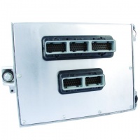
Designed for large scale engine and powertrain (ECM) control, our 128 pin module delivers optimal flexibility for complex control strategies. This ECM is part of the Woodward’s family of electronic control modules with over 1 million units successfully deployed in the field. Built on the proven MPC565 processor, the onboard floating point unit and high clock frequency allow software to be developed in shorter times. Dual CAN 2.0B datalinks ensure interoperability with other vehicle systems. Typical applications include general rapid prototyping, peak/hold fuel injection, and 12 cylinder sequential engines.
Link to MotoHawk help for PCM128
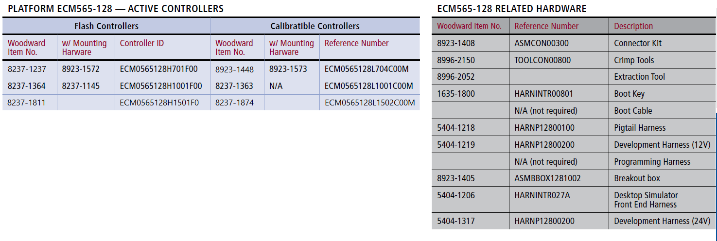
See Product Guide for Active Part Numbers and Related Hardware (Connectors, Harnesses, Bootkey..).
Hardware Features
- Microprocessor: MPC565, 56MHz
- Memory: 1M Flash, 548K RAM, 8K Serial EEPROM,
- 64Kx8 Parallel EEPROM
- Operating Voltage: 9-32VDC
- Operating Temperature: -40° to 105° C
- Sealed connectors operable to 10ft submerged
Inputs
- 30 Analog Inputs
- 4 Low Frequency Discrete Inputs
- 4 VR Frequency Inputs
- 2 Wide Range O2 Sensor Inputs
- Dual Lambda Sensor Interface
- 2 Dual Sensor Wide Band Knock Detectors
Outputs
- 6 3A /1A Peak/Hold Injector Drivers
- 6 7A/3A or 3A/1A Peak/Hold Inj. Drivers
- 16 TTL Level Ignition System Outputs
- 10 3A Low Side PWMs
- 1 1.5A Tachometer Output
- 2 5A H-Bridge PWMs
- 1 10A H-Bridge PWM
- 1 Relay Driver (Main Power)
Datalinks
- 2 CAN 2.0B Channels
- 1 ISO 9141 Channel Note: ISO9141 Hardware is not supported in MotoHawk Software.
- (KWP2000/HWP2000, 10.4kbps)
- 1 RS485 Channel
Part Numbers
Additional Information
There are two main types of PCM128
Hi-Vol
- 1024K Flash
- NO Parallel EEprom (PROD style)
- 32K Serial EE
- 36K RAM
Lo-Vol
- 1024K Flash
- Parallel EEProm (DEV Style)
- 32K Serial EE
- 1024K RAM
MY10 Modules
Due to the EGO IC going EOL, it was required to release new hardware variants of the 128-pin ECUs. These are the ECM-0565-128-1001C/F and the ECM-0565-128-0704C modules. See the module datasheet for specific module details.
MotoHawk 2010bSP0 or higher is required for these ECUs.
The -0704 version is the same as the -0702C version, except with the EGO 1&2 inputs replaced by AN31-34. There is not a corresponding 'F' (PROD) -0704 module because the Flash (PROD) modules did not have the EGO IC.
Changes: ECM-0565-128-1001 (C/F)
- H2 and H3 h-bridges are depopulated
- LSU 4.2 on second UEGO input replaced by LSU 4.9
- AN18 pullup changed to 10k
- EGO1&2 depopulated
- AN31-34 populated
- AN34 changed to 60.4k
- EST9-12 converted to low-side Lamp/LED drivers
ECM-0565-128-0704C
- EGO1&2 depopulated
- AN31-34 populated (AN31,32 are 1M pull-down, AN33,34 are 1k pull-up)
Fault Reporting
LSOs or H-briges
These outputs use a Fault reporting of 0 (ok), 1 (fault) or 2 (indeterminate) that is enabed as a checkbox in the PWM or Discrete Ouptut MotoHawk block. This checkbox creates a fault output port on the block that can be read by the application.
- A fault status of ‘0’ means that the module has read the error status and can determine that a short or open fault is not occurring.
- A status of ‘1’ indicates that the driver has detected a short (to battery or ground) or open fault.
- A fault status of ‘2’ indeterminate means that either it is not possible to determine in the current state whether there is a fault or whether the output is ok, or that the OS has not had an opportunity to detect a fault. A fault status of ‘2’ will also be reported in the case that the fault detection is not supported on the chosen pin (ex. on the injector pins).
The driver can report faults of open circuit, short to ground, and short to battery, but not simultaneously. For example when the load is ON an open circuit cannot be detected – an open can only be detected when the discrete output is off. Similarly, short to battery cannot be detected when the LSO is off. The ‘2’ means indeterminate and means that either the OS has not had opportunity to detect a fault or cannot determine if a fault condition exists. For example, when the discrete output is off and there is not an open circuit, the OS cannot be certain there is not a battery shorted condition and will report a ‘2’. The fault output will be ‘1’ when a fault condition is detected, and a ‘2’ otherwise. The output will not report a ‘0: OK’.
Injector and ESTs
The diagnostics for the injector pins are only supported (in hardware and software) when the outputs are being driven by PSP output blocks (Injector or spark blocks such as Injector Sequence or Multiple PSP).
The fault status from the discrete output block or PWM block when the selected pin is an INJ or EST output will always read a ‘2’. Fault detection of the Injector and ESTs when not driven by PSP output is not supported.
INCA and the 128-pin module
Using INCA to download or upload large calibration tables (maps) can be very resource intensive on the 128-pin ECU. The CPU idle can drop below 10% and cause the application monitor to halt the application, or if the application monitor is not enabled the CPU can be starved for task execution and reset. This is a known issue and is due to the fact that the calibration is written directly to the EEPROM and EEPROM writes are slow. Woodward is investigating improvements to the issue. The following may help:
1. Use MotoHawk 2010a or greater. There were a number of improvements to the CCP handling implemented in 2010a which may benefit this issue.
2. Check the 'Send Command Processor Busy" option in the CCP handler block. This can alert the calibration tool that the ECU is busy writing to EEPROM and to wait.
3. Make sure the CCP block is Idle triggered. There are two CCP blocks - one has external triggers. Use the block with the external triggers and trigger it from Idle.
4. Set the Optimized Up/Download option in INCA to Yes.
5. Try increasing the foreground task and idle task stack in the target definition block.
6. There is also a Starvation Timer block that allows the application designer to set the amount of task starvation time allowed before the watchdog resets the processor. The application developer would want to set this for what makes sense for the application (ex. in the event of an infinate loop), but extending this time may allow additional time for calibration with INCA.
FAQ
What's special about EST13 to EST16?
- These pins have stronger LowSide Drivers and can sync higher current
- The hardware can be configured as PUSH_PULL or LOW_SIDE drive
- Current MotoHawk sets the DriverMode to LOW_SIDE for DIO, OneShot and to PUSH_PULL for PWM.
- The Hi-Vol PCM128 does not have pull-up transistors, so technically cannot be configured as PUSH_PULL but the polarity remains active high.
- When instantiating from ControlCore as a LOW_SIDE it makes them active low instead of active high.
Tips
- Think of EST1-12 and EST13-16 as two separate banks
- Avoid mixing Behaviours within a bank where possible, as it can potentially restrict DriverModes and Diagnostic Capability.
Why am I getting a ERROR_DRIVER_CONFLICT?
Where have DG5, 6,7,8 Gone?
You will get "Hardware Not Supported" if you use a Low-Vol. These resources are consumed as part of the KNOCK2 device.
Where is my KNOCK2?
The Hi-Vol only has KNOCK1
Does 128-pin module have the option of software selectable pullup resistors
No, the pullups are not configurable. Selecting the 'Strong' vs 'Weak' pullup in the Encoder Defintition block does not change any value.
An external 2.2k pullup resistor may be needed with open-collector type crank and cam sensors.
Why do I have an CECUServer:WriteECU- MWWriteECU error when calibrating a display value in MotoTune
This error will occur if a model built for a 128-pin ECU is programmed into a MY10 ECU, and the version of MotoHawk is too old to support the new model hardware. MotoHawk 2010bSP0 or higher is required for ECM-565-128-1001C/F or ECM-565-128-0704C.
What do the fault outputs of '0', '1', or '2' mean on the Digital Output or PWM block?
- A fault status of ‘0’ means that the module has read the error status and can determine that a short or open fault is not occurring.
- A status of ‘1’ indicates that the driver has detected a short (to battery or ground) or open fault.
- A fault status of ‘2’ indeterminate means that either it is not possible to determine in the current state whether there is a fault or whether the output is ok, or that the OS has not had an opportunity to detect a fault. A fault status of ‘2’ will also be reported in the case that the fault detection is not supported on the chosen pin (ex. on the injector pins).
I will use the LSO’s as an example. The LSOs use a PreFET driver IC called a TPIC to provide the diagnostic information. Faults of open circuit, short to ground, and short to battery can be detected, but not simultaneously. For example when the load is ON an open circuit cannot be detected – an open can only be detected when the discrete output is off. Similarly, short to battery cannot be detected when the LSO is off. The ‘2’ means indeterminate and means that either the OS has not had opportunity to detect a fault or cannot determine if a fault condition exists. For example, when the discrete output is off and there is not an open circuit, the OS cannot be certain there is not a battery shorted condition and will report a ‘2’. The fault output will be ‘1’ when a fault condition is detected, and a ‘2’ otherwise. The output will not report a ‘0: OK’.
How are diagnostics for injector pins supported? The fault output port always reports a '2' Indeterminate
The diagnostics for the injector pins are only supported (in hardware and software) when the outputs are being driven by PSP output blocks (Injector blocks). The fault status from the discrete output block when the selected pin is an INJ Output will always read a ‘2’ in this case.
Is the Flexible Encoder Supported on the 128-pin module?
No, the Flexible Encoder requires enhanced TPU or eTPU. The flexible encoder cannot be supported on the 128-pin's TPU - the hardware is not capable of this.

