Difference between revisions of "48-pin Module Family"
m (Added link to the webstore) |
m (All 48 pin hardware is obsolete) |
||
| Line 4: | Line 4: | ||
==ECM-0563-048== | ==ECM-0563-048== | ||
| + | <span style="color:red"><b>(OBSOLETE)</b></span> | ||
===Hardware Features=== | ===Hardware Features=== | ||
| Line 34: | Line 35: | ||
GHS 3.6, 4.2.1, or 4.2.4 version required, GCC may be used also. | GHS 3.6, 4.2.1, or 4.2.4 version required, GCC may be used also. | ||
| − | === Part Numbers=== | + | === Part Numbers=== |
| + | <span style="color:red"><b>(All Obsolete)</b></span> | ||
[[Image: ECM48563_pn.png]] | [[Image: ECM48563_pn.png]] | ||
| Line 57: | Line 59: | ||
==GCM-0563-048 General Control Module== | ==GCM-0563-048 General Control Module== | ||
| + | <span style="color:red"><b>(OBSOLETE)</b></span> | ||
===Hardware Features=== | ===Hardware Features=== | ||
| Line 87: | Line 90: | ||
=== Part Numbers=== | === Part Numbers=== | ||
| + | <span style="color:red"><b>(All Obsolete)</b></span> | ||
[[Image: GCM48_pn.png]] | [[Image: GCM48_pn.png]] | ||
| Line 108: | Line 112: | ||
==HCM-0563-048 Hydraulic Control Module == | ==HCM-0563-048 Hydraulic Control Module == | ||
| + | <span style="color:red"><b>(OBSOLETE)</b></span> | ||
| + | |||
===Hardware Features=== | ===Hardware Features=== | ||
:Microprocessor: MPC563, 40MHz | :Microprocessor: MPC563, 40MHz | ||
| Line 136: | Line 142: | ||
=== Part Numbers=== | === Part Numbers=== | ||
| + | <span style="color:red"><b>(All Obsolete)</b></span> | ||
[[Image: HCM48_pn.png]] | [[Image: HCM48_pn.png]] | ||
| Line 158: | Line 165: | ||
== ECM-0555-048 == | == ECM-0555-048 == | ||
| + | <span style="color:red"><b>(OBSOLETE)</b></span> | ||
===Hardware Features=== | ===Hardware Features=== | ||
| Line 188: | Line 196: | ||
=== Part Numbers=== | === Part Numbers=== | ||
| + | <span style="color:red"><b>(All Obsolete)</b></span> | ||
[[Image: ECM48555_pn.png ]] | [[Image: ECM48555_pn.png ]] | ||
[[Category:Modules|48-pin Module Family]] | [[Category:Modules|48-pin Module Family]] | ||
Latest revision as of 14:12, 15 March 2024
See Product Guide for Detailed Part Numbers of Modules and Related Part Numbers (Harnesses, Connectors..) as well as Block Diagram IO comparisons.
Contents
ECM-0563-048
(OBSOLETE)
Hardware Features
- Microprocessor: MPC563, 56MHz
- Memory: 512K Flash*, 32K RAM(24K+4K overlayable)
- 128K parallel EEPROM (ECM-0563-048-0701-C)
- Operating Voltage: 8-16VDC
- Operating Temperature: -40° to 105° C
- Sealed Connectors Operable to 10ft submerged
Note: DEV vs PROD Flash Memory The 48-pin modules have 512k Flash memory, but not all of that is available for general use. 64k of this memory is reserved for Module Configuration and Hardboot and cannot be used by the application. The PROD module will also have an additional 64k less memory because 64k of flash is reserved for calibration space. The calibrations for the DEV module are stored in a parallel EEPROM, so the 64k of flash is not reserved.
Inputs
- 13 Analog Inputs
- 2 VR/HallFrequency Inputs
Outputs
- 4 Low Side Injector Drivers
- 8 TTL Level Ignition System Outputs
- 5 High Current Low Side PWMs
- 2 5A H-Bridge PWMs with Current Feedback
- Independent Transducer Power Supply
- 1 Low SideRelay Driver (Main Power)
Datalinks
- 1 CAN 2.0B Channel
Notes GHS 3.6, 4.2.1, or 4.2.4 version required, GCC may be used also.
Part Numbers
BUY NOW
1751-6110 ECM-0563-048-0705 PROD (1751-6068) with mounting hardware
ECM Differences:
ECM-0563-048-0701: 1 CAN channel, 13 analog inputs, 2 digital/VR inputs, 4 injector/low-side drivers, 8 TTL spark timing outputs, 5 low-side drivers, 2 H-bridges, one Main Power Relay low-side driver.
ECM-0563-048-0705: similar to ECM-0563-048-0701 module, including same pull-up / pull-down resistors, but only has 1 H-bridge and has 2 more low-side drivers.
ECM-0563-048-0806: same as ECM-0563-048-0705 module, but with different boot code
ECM-0563-048-0704: same features as ECM-0563-048-0705, but pull-up / pull-down resistors are different.
FAQ
I have a model that builds on the DEV module, but on the PROD the build fails with an out of flash memory link error: (error) section .romcals (0x6ff8c-0x70e3b) doesn't fit in memory block FLASH (0x10100-0x6ffff). The PROD module has effectively 64k less general purpose flash than the DEV module because a fixed 64k is reserved to store calibrations on the PROD module. The DEV module stores these calibrations in parallel EEPROM so this space is not reserved.
I am getting the out of memory build error described above, but the build statistics show that there is flash available There is an error in the build stats where the 64k reserved for calibration is counted twice. This is a known issue, and will be fixed in a future release.
GCM-0563-048 General Control Module
(OBSOLETE)
Hardware Features
- Microprocessor: MPC563, 40MHz
- Memory: 512K Flash, 32K RAM (4K overlayable)
- 16K serial EEPROM
- 128K parallel EEPROM (GCM-0563-048-0801-C)
- Operating Voltage: 8-32VDC
- Operating Temperature: -40° to 105° C
- Sealed Connectors Operable to 10ft. submerged
Inputs
- Up to 16 Analog Inputs
- Up to 7 Discrete/Frequency Inputs
- Up to 2 VR/Hall Frequency Inputs
- 1 Emergency Stop Input
Outputs
- 2 3A Low Side Drivers w/Current Feedback
- 4 3A Low Side Drivers
- 2 2.9A High Side Drivers
- 1 1A EasyLink/Low Side Driver
- 1 Relay Driver (Main Power)
- 1 10A H-Bridge Driver
Datalinks
- 3 CAN 2.0B Channels
NOTE: CAN-1 must be used for programming
Part Numbers
Part number 1751-6332 is also GCM05630480804F00.
Part number 1751-6509 is also GCM05630480804CP0.
Part number 1751-6692 supersedes 1751-6332 as GCM05630480806F00; However the new part has depopulated the hbridge output (H1).
8923-2109 is the kitted version of 1751-6692.
Part number 1751-6326 is also GCM05630480803F00.
Part number 1751-6508 is also GCM05630480803CP0.
Frequently Asked Questions
Can I use voltages over 5V on the analog channels?
Using voltage over 5V is not recommended on analogs with Pull Up resistors. The analogs with 220k PD can handle 24V input.
What is the one Digital Output pin that is indicated for the datasheet for GCM-563-048-0802?
The GCM-563-048-0802 block diagram in the data sheet (36303) shows 7 Low Side Driver type outputs labeled LSO1 through LSO7. LSO1 through LSO6 are the Low Side Driver outputs mentioned in the data sheet (36303). LSO7 is the digital output mentioned in the data sheet (36303).
The output stage of the LSO7 output is a lowside MOSFET with a diode protected 200Ohm pull-up to 5V. Thus the output will pull to 5V when the MOSFET is OFF, which is why it is referred to as a digital output. The other LSOs do not have this pull-up
HCM-0563-048 Hydraulic Control Module
(OBSOLETE)
Hardware Features
- Microprocessor: MPC563, 40MHz
- Memory: 512K Flash, 32K RAM (4K overlayable)
- 16K serial EEPROM
- 128K parallel EEPROM
- Operating Voltage: 8-32VDC
- Operating Temperature: -40° to 85° C
- Sealed Connectors Operable to 10ft. submerged
Inputs
- Up to 16 Analog Inputs
- Up to 6 Discrete/Frequency Inputs
- Up to 2 VR/Hall Frequency Inputs
- 1 Knock/Drive Noise Detector Input
- 1 Stop Input
Outputs
- 6 2.5A Low Side Drivers w/Current Feedback
- 4 3A Low Side Drivers
- 1 1A EasyLink/Low Side Driver
- 1 Relay Driver (Main Power)
Datalinks
- 2 CAN 2.0B Channels
NOTE: CAN-1 must be used for programming
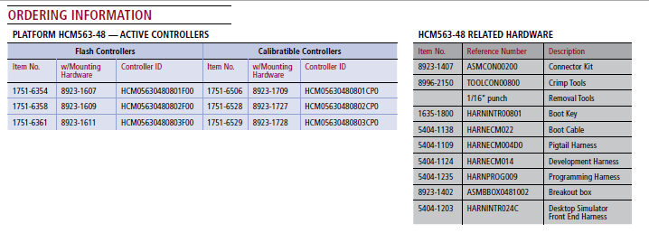
Part Numbers
Part number 1751-6354 is also HCM05630480804F00
Part number 1751-6358 is also HCM05630480805F00
Part number 1751-6361 is also HCM05630480806F00
Part number 1751-6506 is also HCM05630480804CP0
Part number 1751-6528 is also HCM05630480805CP0
Part number 1751-6529 is also HCM05630480806CP0
BUY NOW
8923-1611 HCM563-48-0803 PROD (1751-6361) with mounting hardware
HCM Frequently Asked Questions
What are the maximum measurable input frequencies?
The maximum frequency that the hardware can accept is defined as the filter time constant for the pin. For example the data sheet for HCM-0563-048-0803 (36332_B) says VR1 inputs have a time constant of 100us. 1/100us = 10KHz. Software performance of a frequency input in terms of maximum frequency is controller specific. It is dependent on the underlying silicon sub-unit that the pin is connected to (E.g. MIOS or TPU) and the software implementation. The 48-pin modules have silicon that should allow most frequencies to be read, but very high frequency readings may become granular depending on the input pin type.
Note: CRANK/CAM speed inputs often have a stronger filter than digital inputs.
ECM-0555-048
(OBSOLETE)
Hardware Features
- Microprocessor: Freescale MPC555, 40MHz
- Memory: 448K Flash, 26K RAM,
- 4K serial EEPROM Flash, Except: 0710 - 8K serial EEPROM
- Calibratible Memory: 64K parallel EEPROM
- Operating Voltage: 8-16VDC
- Operating Temperature: -40° to 85° C (in benchmark marine engine application)
- Sealed Connectors Operable to 10 ft. submerged
Inputs
- 12 to 15 Analog Inputs
- 3 or 4 Low Frequency Digital Inputs
- 1 or 2 Hall Effect Frequency Inputs (cam)
- 0 or 1 Variable Reluctance Frequency Input (crank)
- 0 to 2 Knock Sensor Inputs
- 1 Stop Input
Outputs*
- 4 Injector Driver Outputs
- 1 to 4 Electronic Spark Trigger (5V) Ouputs
- 1 Tachometer Output
- 4 or 5 Low Side Outputs
- 1 Main Power Relay Driver Output
Datalinks
- 1 CAN 2.0B Channel
- 1 RS-485 Channel


