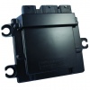
PCM112-14
Contents
Module
Overview
The PCM112-14 is another module in the Woodward 112 pin module family. It is well suited for application which are presently utilizing the PCM09 module.
Power Requirements
The PCM112-14 module is designed for a nominal voltage of 12 Vdc.
MotoHawk Requirements
MotoHawk 2014aSP0 or higher is required for PCM112-14.
This means Matlab 2012a or higher is required, as MotoHawk supports Matlab 2 years backward.
Compilers
Main Micro: Green Hills 4.2.4 or GCC PowerPC eabi SPE 4.6
Auxillary: Freescale CodeWarrior 4.6
Targets
The PCM112-14 has different Targets for the MAIN and the S12G auxillary processor as shown below:
Main Processor
1751-6685: Target ECM-5644A-112-064-1400
Auxillary Processor
- Target ECM-S12G-112-063-1400 PROD Only
Datasheets
In development
I/O Behaviors
Related Part Numbers
| Part Number | Description |
|---|---|
| 8923-1413 | Connector Kit |
| 8996-2158 8996-2159 |
Crimp Tools |
| 8996-1059 8996-2161 |
Removal Tools |
| 1635-1800 | Boot Key |
| 5404-1215 | Pig Tail |
| TDB | Development Harness |
| TDB | Programming Harness |
| 8923-1404 | Breakout Box |
| TBD | Desktop Simulator Harness |
Internal Temperature Monitor
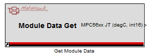
The SECM112 has an internal temperature monitor that can be accessed via the Get Module Data block. So, for example, you could implement a Simulink model that logged the maximum observed MicroTemp to NVM.
Calibration Memory
The PCM112-14 has 64k of Calibration memory available.
If you are porting an application from another ECU (ex. the 128-pin) the PCM112-14 may have less calibration memory available. There is a second 64k of Calibration Flash that can be used to shadow this data so that in the event of a power loss during calibration a copy of the calibration data is stored (from the last write). This redundant calibration is enabled with a special blockset. However, the PCM112-14 has 64k of Calibration Flash memory, regardless of whether redundant calibration is enabled or not. The second 64k cannot be used to store additional calibrations. This was a design decision based on the total memory of the DEV module. For the DEV module, calibration data is shadowed from flash into RAM at startup to allow on-line calibration. The PCM112-14 has limited RAM as compared to some of the other ECUs with external RAM. If additional calibration flash was allocated, the same amount of RAM would need to be reserved and would not be available to the application. For the Flash memory layout, the calibration data is read directly from Flash and is not shadowed into RAM.
The PCM112-14 also has 16k of NV memory storage in serial EEPROM. The NV data (for both DEV or PROD) is shadowed in RAM at startup, and is stored in the serial EEPROM at shutdown through execution of the store NV block. Some calibration values may be able to be moved to NV storage (ex. Calibration NV).
Recommendations to reduce calibration memory in the application:
1. Review and Optimize Datatypes. The first thing to look at in reducing calibration memory is 64 bit vs 32 bit. Double is the Simulink default, but is often larger than required. Convert calibratons to 32-bit (single) or smaller datatypes.
2. Review and Optimize Tables. The next big item is table optimizations. It is likely that 32-bit floating point is not needed for every table and can be reduced. Reducing the dimenstions of tables would also reduce the memory usage.
Recovering the PCM112-14
Occasionally, errors in programming may require that the module be recovered with a boot key or boot sequence. The following section describes recovery procedure for the PCM112-14. For more information, see Boot Key Recovery.
Important: Remove the ECU from all control connections before attempting to recover the module.
Default Bootloader MotoServer Settings (Recover/Bootstrap Mode):
Main Core: 250kbps on CAN-1, City ID 0x0B (11)
S12G Core: 250kbps on CAN-1, City ID 0x81 (129)
The PCM112-14 has two microprocessor cores, the Main Core and the Auxillary S12G. Both processors are connected on CAN1, so it is important that both processors configure their CAN-1 port with the same baud rate, and different MotoTune IDs.
Recovering the Main Processor
Section to be developed.
Recovering the S12G Auxillary Core (requires battery toggle)
Section to be developed.
Applying the boot signal or sequence
The boot key signal or boot sequence is only searched within the first 2-3 seconds of the ECU waking up. To ensure that the signal/sequence is recognized, the following procedure is recommended:
1) Apply the boot signal or sequence.
2) Main Core recovery: Turn Power ON, but key off; S12G Core recovery: battery off.
3) Initiate MotoTune programming on the MotoServer port (City ID 0x0B 250k baud for Main Core, 0x081 250kbaud for S12G Core).
4) When 'Searching for ECU' appears in MotoTune, turn the key on (Main Core recovery) or battery on (S12G Core recovery). It may take several tries.

