 |
|
|
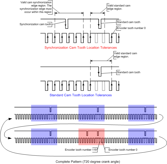
This encoder style consists of 'Y' groups of 'N' Teeth where 'X' teeth in each group have been removed. The figure illustrates the pattern for 'Y' equal to three, 'N' equal to tweleve and 'X' equal to two.
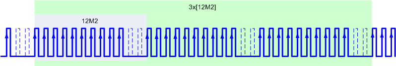
This encoder style is reliant upon a secondary signal like a cam existing within the system that allows one of the teeth groups to be distinguished from the others. The encoder observes cam events and associates such events with a group or group of teeth on the primary encoder. A crank synchronization error will results if the tracked position does not match the calculated the position when a cam event is observed. A crank synchronization error is also flagged if the number of teeth in a group does not match the expected number of teeth. For the previous figure an error would result if 10 teeth were not observed between a pair of missing teeth. For the Halfmoon example the expected tooth count between missing teeth pairs would be two.
A resynchronization can temporarily impact the behavior of crank-synchronous blocks. Impacts include a pulse not scheduling as expected, having it occur twice, or being malformed. The system will recover, but the initial impact is unavoidable because the correction to the crank angle position results in a step change in position that may disrupt the underlying pulse scheduling software.
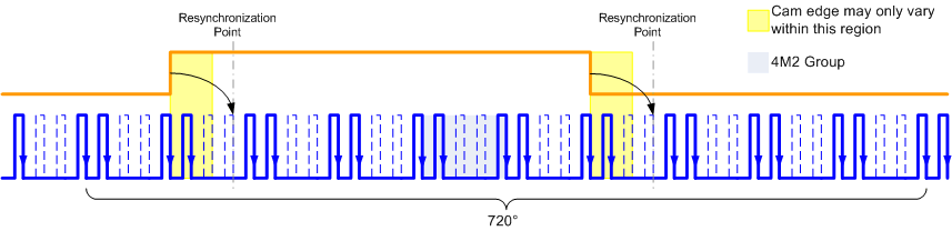
Each edge of the halfmoon must fall inside the same tooth "group" for all engine operating conditions. The edge must also occur at least one tooth period before the next physical tooth, as has been highlighted in the figure. Unreliable crank encoder synchronization may occur (which will lead to encoder errors) if an edge transition were to occur outside the specified region.
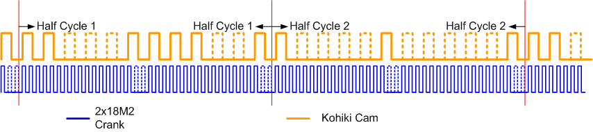
A cam error will be reported if the width does not conform to the following:
The cam to crank phase relationship needs to match what is depicted in the figure.
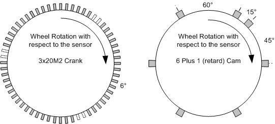
Details on this cam phaser can be found here.
| Copyright 2009 Woodward Corporation. All Rights Reserved. | Visit Us: mcs.woodward.com |