 |
|
|
This MotoHawk™ block allows the last reported cam position, cam velocity and time between position reporting events to be read for the supported variable cam phaser patterns.
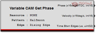
motohawk_variable_cam_phase
MotoHawk_lib/Advanced Digital I/O
This MotoHawk™ block allows the last reported cam position, cam velocity and time between position reporting events to be read for the supported variable cam phaser patterns. This block can be used in conjunction with the Variable Cam Trigger block to trigger when a new report is available.
There are module specific variable cam considerations that must be taken into account when using this capability.
Phase refers to the current position of the cam relative to the crank encoder as an absolute crank angle position. Typically this absolute position is converted into a relative position. To execute such a conversion requires an understanding of the cam's topology and thus where position reports could occur. An example the 6 tooth PWM cam has 6 teeth evenly distributed about the cycle, which means a report shall arrive every 120 crank angle degrees (degCA) as the figure illustrates.
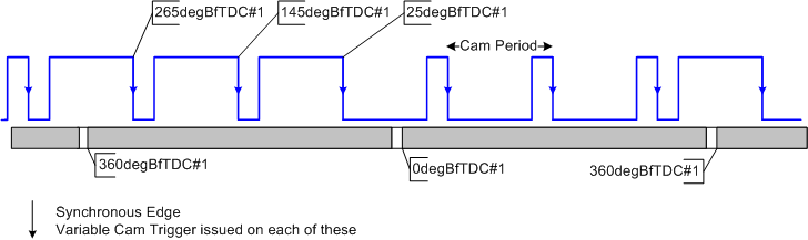
Taking the modulus of the reported value with 120 will translate the absolute position into a relative value. From the figure 145 modulus 120 is 25degCA as is 25 modulus 120. So the relative cam position has not moved in this example. If the zero position (also called the hard stop) was known to be at 20 degBfTDC#1 then the cam's relative position would be 5 degCA. This value could be used as the feedback term for a variable cam phaser position controller.
The velocity attribute is useful as a feed forward element for a position controller that is executing in the time domain. The timing of feedback information is dependant upon the number of reporting teeth in the cam pattern and also on the engine speed. The velocity can be used to provide an updated estimate of what the cam position would be X milliseconds after the report was observed. If a 6 tooth PWM cam was in use and the engine was spinning at 1000RPM then a position report would be issued every 20ms. But a position controller executing every 5ms does not want to use the same position 4 times as that will lead to integrator windup. So the velocity is used to adjust the cam position being fed to the position controller. For example, if the cam reports that it is moving at 50degCA/s and its relative position was say 7.00degCA then the position after 5ms could be estimated as 7.25degCA instead of keeping the 7.00degCA position.
Velocity is calculated by MotoHawk™ based upon the time between neighbouring reports.
The time between edges attribute defines the time between triggers (which is synonomous with edges).
MotoHawk™ can support more than one variable cam phaser by having each separate cam phaser utilizing an instance of this block to define it. However only one of these cam phasers is used to provide half cycle information to the crank encoder. The cam phaser that is instantiated on the CAM resource is always used for engine sychronization purposes. Therefore one of the cam phasers in a system should always utilize the CAM resource before other cam phaser resources are consumed. Additionaly the "CAM Pattern" selection made in the Encoder Definition block should match the selection made here.
| Parameter Field | Values | Comments/Description |
|---|---|---|
| Resource | Drop-down list | Creates variable cam phaser support on the selected resource. Note that selecting the CAM resource implies that it shall be used for engine synchronization. See Encoder Definition block. |
| CAM Pattern | Drop-down list | Select appropriate pattern. Note that some resources are incapable of supporting some patterns due to hardware limitations. A "Cam Pattern Unsupported" error likely means that the selected resource is unable to handle the chosen pattern |
| Edge Detect | Rising, Falling, Either | Select the synchronous edge of the signal. |
| Allow I/O pin to be calibrated | Check box | Name, Access Levels and Instrumentation Group fields available. This field is only available on Classic modules, see ModuleTypes for help. |
| Name | Alpha-numeric text, quote enclosed | Name assigned to the resource. Should be unique and C-legal (no special characters such as spaces, dashes or commas (underscore allowed). |
| Read Access Level | 0-8 | Sets security level 1 lowest, 8 highest, for user access to read value. A setting of zero indicates unsecured access is allowed. |
| Write Access Level | 0-8 | Sets security level 1 lowest, 8 highest, for user access to write value. A setting of zero indicates unsecured access is allowed. |
| Pin Instrumentation Group | Alpha-numeric text, single-quote enclosed | Defines the desired Folder name and hierarchy to be used by suitable Instrumentation Tools. Use "|" character between folder names to delineate subfolder structure. |
| Calibration Parameters Instrumentation Group | Alpha-numeric text, single-quote enclosed | Defines the desired Folder name and hierarchy to be used by suitable Instrumentation Tools. Use "|" character between folder names to delineate subfolder structure. |
| Copyright 2009-2014 Woodward Corporation. All Rights Reserved. | Visit Us: mcs.woodward.com |