
Modbus Client Definition
This licensed MotoHawk™ block defines Modbus Client (Master) device for Serial or Ethernet protocol type..
Block ID
Modbus Client Definition
Library
motohawk_modbus_lib/Modbus Client Definition
Description
The MotoHawk Modbus library is a separately licensed product, therefore the user's MotoHawk security token will need to have the license added to it. For instructions on how to accomplish this, please see the instructions for adding the MotoHawk Modbus Library license.
A user can check whether their MotoHawk security token has the needed product license at the Matlab command line by executing the woodward_custom_modbus_check_license command. A returned value of 1 means the MotoHawk Modbus Library is licensed, while a returned value of 0 means it is not.
Modbus Client Definition block defines a Modbus client. A Modbus Client Request allows the user to post a request to a Server, and read the result using the Modbus Client Response block. Notification that a response is available can be determined by polling the Modbus Client Response block or using the Modbus Client Response Trigger block
Click here for example usage
Communication between Client and Modbus Server device, called later a transaction, is implemented by means of PDU frames. The mapping of a Modbus protocol on specific buses introduce additional fields on the application data unit (ADU) as is shown on the diagram below.
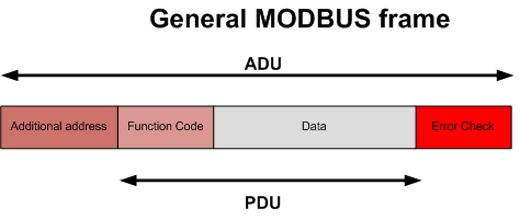
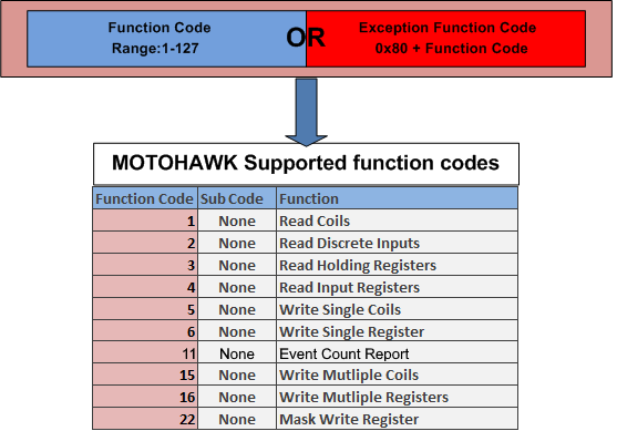
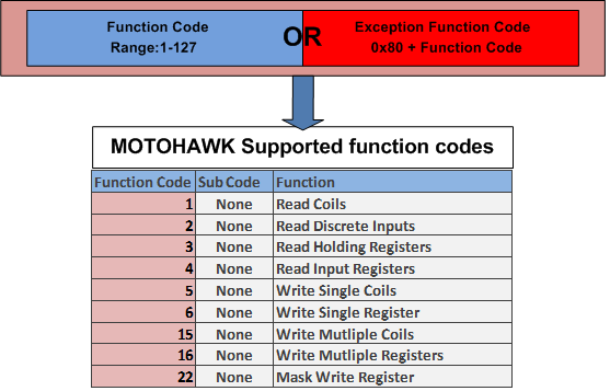
The Modbus Application Data Unit (ADU) is built by a Client that initiates the Modbus transaction. A Function code informs the Server device what kind of action to perform. Valid codes are in range of 1..255 (128-255 reserved by exception codes).
The data field sent from a Client to a Server contains additional information that the Server uses to take action defined by the function code. This could contain discrete and register addresses, the quantity of items to be handled etc. When a Server responds to the Client request it uses the function code field to indicate either a normal (error-free) response or an exception response. For details please go to related Modbus request blocks.
Serial
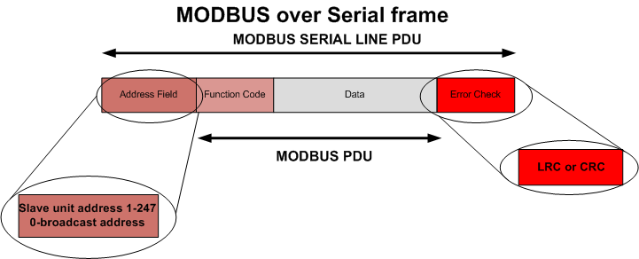
The address field allows to address up to 247 Servers connected to the same bus. A Client initiates only one MODBUS transaction at a time and Servers will never transmit data without receiving a request from the Client.
The Client issues requests to Servers in two modes:
Unicast Mode (Address 1-247): Client addresses an individual Server. After receiving and processing the request, the Server returns a result to the Client. This Mode is supported by all of the Motohawk Modbus blocks.
Broadcast Mode (Address 0): Client sends a request to all Servers. No response is returned. Supported only by Motohawk Modbus Write Request Function Types: Mask Holding Register, Write Coil and Write Holding Register.
Error checking field is the result of a "Redundancy Checking" calculation that is performed on the message content. The are two kinds of calculation methods which are used depending on the transmission mode being used (RTU : CRC16 or ASCII : LRC). For more information please refer to Modbus over Serial line Specification and implementation guide .
Note: Size of the referenced Serial Definition block queue should be 256B for RTU and 513B for ASCII protocol type. Otherwise a long Modbus message may be missed.
Motohawk Serial implementation limits the supported function codes per the table below
Ethernet
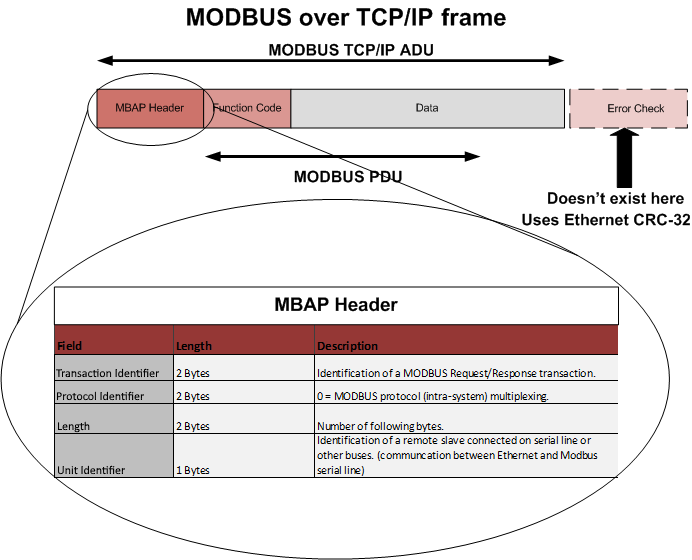
The MODBUS Client allows the user application to explicitly control information exchange with a remote device (Server). The Client builds a MODBUS request and sends it to the remove Server listening on 502 TCP port (configurable through Remote Port parameter). Since the Modbus Ethernet communication requires the establishment of a TCP connection between a Client and a Server using its IP address, the Modbus Unit Identifier (Server ID) is used only for intra-system routing purpose. It can be used to communicate to a MODBUS+ or a MODBUS serial line slave through a gateway between an Ethernet TCP-IP network and a MODBUS serial line. This field is optionally set by the MODBUS Client in the Modbus Client Request and must be returned with the same value in the response by the server.
Motohawk Ethernet implementation limits the supported function codes per the table below
Associated Blocks
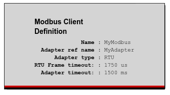
Block Parameters
| Parameter Field | Values | Comments/Description |
|---|---|---|
| Name | String | This parameter defines unique identifier which is used as a reference for request definition blocks. |
| Adapter definition reference name | String | Reference to they adapter definition block. For example the adapter could be a Serial or Ethernet definition. |
| Adapter type | Drop-down list | Defines the protocol type (ASCII, RTU, TCP) which implicitly defines the adapter that is needed. |
| Maximum number of connections | 1-16 | Shown only for TCP. Defines the maximum number of simultaneous MODBUS connections the Client (Client) can handle |
| Remote Port | 1-65535 | Shown only for TCP. Defines the Ethernet port used for communication with the Server |
| Adapter timeout* | 50-10000 [ms] | Defines the period of time before Client aborts the transaction in case no response from Server device is received. |
| Use custom frame timeout | Check Box | When checked allows to specify a custom RTU frame timeout. This field is visible only for RTU protocol type. If this option is not used, the default timeout is based on baud rate selection: 1750us for baud rates greater than 19200 and 3.5 character time otherwise. |
| Frame Timeout[us]* | 1000-100000 [us] | Specifies a custom RTU frame timeout. |
| Allow parameters marked with * to be calibrated | Check Box (enable) | Allows attributes marked with (*) to be calibrated |
| Read access level | 0-8 | Sets security level 0 lowest, 8 highest, for user access to read value |
| Write Access Level | 0-8 | Sets security level 0 lowest, 8 highest, for user access to write value |
| Instrumentation Group | Alpha-numeric text | Determines Folder name and hierarchy. Use "|" character between folder names to delineate subgroup structure |