 |
|
|
An Absolute Source refers to an encoder source that may be used by the encoder system to provide crank synchronous behaviors (like injection) with a high resolution tooth interpolated absolute crank angle position. The actual resolution of the interpolation is dependent upon the number of teeth of the wheel, but in general it will be 0.0625 degrees crank angle. A Companion Source is also an encoder source except that it is not used to provide absolute crank angle position. Companion sources are used to help synchronize an absolute source (e.g. tooth synchronizer pattern) and/or provide halfcycle information (e.g. camshaft pattern). A different Absolute Source can also be used as a companion like a 60M2 on the crank with 6+1 on the cam. This would be done if encoder redundancy was to be supported.
The motohawk_flexencoder_project script can be used to create a sample flexible encoder application. Different types of system can be created with this script.
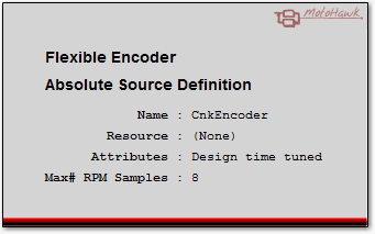
Absolute Source Definition
motohawk_flexenc_lib
| Parameter Field | Values | Comments/Description | Calibration Name |
|---|---|---|---|
| Name | Alpha-numeric text, quote enclosed |
Name of the encoder source that other blocks will use to reference this definition. This value must be referenced by an
Encoder System within its
Crank Source Position entry before it will create and be useable. This name is also used in the construction of the names of attributes that support calibration. |
|
| Resource | Drop down list | The list of resources that are capable of supporting this behavior. There is often fewer resources with the capability of supporting absolute crank angle position determination when compared to Companion Sources. | |
| Define Enumeration Order | Check box |
Check to allow the application to control the order that Flexible Encoder sources are enumerated by the system. This can be useful
when using calibration tools that deal directly with the value rather than the enumeration. Controlling the enumeration order for
all sources in the model will ensure that the same value is always associated to the same source. Source's may need to support
enumeration when options like flexible connectivity are utilized. The This Source ID attribute of the Get Source Info block reflects how the system enumerated the source. |
|
| Order | numeric | This value controls how Flexible Encoder sources are enumerated. A low value will enumerate before another source that has a higher value. Those sources that have not checked the Define Enumeration Order will be considered before those sources that do have Define Enumeration Order checked. |
| Parameter Field | Values | Comments/Description | Calibration Name |
|---|---|---|---|
| Pattern Selector | Alpha-numeric text, quote enclosed | This text associates this absolute encoder source definition with an encoder pattern definition. The name used by the Flexible Encoder Pattern Definition that is to be referenced should be used here. | {Name}_PatternSelector |
| Create Source | Check box (True/False) |
Check this box to have the application create this source. Defining the source without creating it (not checked) reserves the software resources necessary to support this encoder source, but won't physically create that source. This box is normally checked and needs to be checked if the source does not support calibration. Calibration control of the creation allows a source to be disabled so that it can't influence the system, which is often a desired outcome when using flexible connectivity. | {Name}_CreateSource |
| Num Revs Per Cycle | 1 or 2 | Defines how many times this encoder source will revolve in an engine cycle. A crankshaft encoder source used in a 4-stroke application will revolve twice per cycle where as a camshaft source would only revolve once. | {Name}_NumRevsPerCycle |
| Is Rising Edge Sync | Falling Edge(False) Rising Edge(True) by Drop Down |
Defines the signal edge that represents absolute crank angle position. This should align to the edge that defines the LogicalDeg entry of the associated encoder pattern. This attribute is only considered when digital sensing technologies are in use. A resource that has a Variable Reluctance input stage will, by default, ignore this setting as the edge to use is defined by the hardware circuit rather than by the pattern itself. Uncheck the Hardware Sets VR Edge Sync attribute to override this default behavior and allow the Is Rising Edge Sync setting to be used with an input that has a VR interface. | {Name}_IsRisingEdgeSync |
| Hardware Sets VR Edge Sync | Check box | This setting only applies when a Variable Reluctance interface is in use. MotoHawk determines which edge to use automatically when this attribute is checked (which is the default). MotoHawk will only use the Is Rising Edge Sync setting for synchronous edge determination when this attribute is not checked. VR Signals are discussed further here. | {Name}_HardwareSetsVREdgeSync |
| Good Keys to Clear Fault | Numeric, 1 to 255 | Internal behavior is sometimes dictated by whether the encoder system believes that the source is in error. For example an encoder that suffers from a loss of signal fault may require a number of good key matches to occur before the source is said to now be good. This is more often used to ratify whether a companion source is considered valid, like whether a camshaft signal can be trusted to provide halfcycle information. The larger the value the longer it will take for the encoder to be considered valid again. | {Name}_GoodKeysToClrFault |
| Key Aligns (with companion source) | Check box | When checked (True) this attribute signifies that a key event of this source aligns with teeth of this source's Loss Companion. This is most notably seen on single tooth halfcycle and synchronizing companion sources. See here for a detailed explanation on when to check or uncheck this attribute. | {Name}_KeyAligns |
| Phase Reporting | Drop Down | Indicates the phase reporting capability of this source. See here for details on how to configure this attribute. |
{Name}_PhaseReportingCondition This calibration attribute is available provided the mask attribute was not set to Not Created. |
| Override System Zero Speed Timeout | Checkbox | Check to allow this source to specify its own Zero Speed Timeout instead of using the system level Zero Speed Timeout. | |
| Zero Speed Timeout (ms) | Integer zero or greater |
Defines the time without any activity on this source before this encoder source considers that it has observed a zero speed condition. So a value of
1000 implies that if this encoder source does not observe any teeth in 1000ms then it will be considered to have observed a zero speed condition. The
Encoder State will report ZERO_SPEED if this source is the active source. The system level Zero Speed Timeout will be used instead of this value unless Override System Zero Speed Timeout is checked or if a timeout of zero is specified. |
{Name}_ZeroSpeedTimeout This calibration attribute is available when Override System Zero Speed Timeout is checked. |
| Parameter Field | Values | Comments/Description | Calibration Name |
|---|---|---|---|
| Has Loss Companion | Check box | Signifies that this source has a companion source that it will use to detect loss of this encoder's signal. Loss is flagged if this source detects a certain number of teeth on another source. Observing teeth on the companion without observing teeth on this source implies that the other source is rotating yet this source is not being seen to rotate. | |
| Name of Loss Companion | Alpha-numeric text, quote enclosed | Name of the encoder source that this source shall use to detect loss. Should be the name of another absolute or companion source block. If this source(a) is to operate as either a halfcycle and/or synchronization companion for another source(b) then this source(a) needs to use source(b) as its loss companion. | |
| Teeth Before Loss | Integer greater than one | The number of teeth that need to be observed by the referenced encoder source (Name of Loss Companion) without a tooth being observed on this encoder source before this encoder source is considered to have suffered a loss failure. Consider a 4-stroke 60M2 crank used with a tooth cam. The crank would only need to observe two teeth on the cam before it could be considered to have suffered loss (can't be one because that would indicate a fault each time a tooth was observed). The cam could conceivably observe all 58 teeth (has two missing so it is not 60) twice (because it rotates twice as fast as the cam) and still not have observed the cam. But observe 1 more and that could indicate loss. In other words the cam's Teeth Before Loss should be at least 117 for this case. | {Name}_LossCompanion_TeethBeforeLoss This calibration attribute is available provided Has Loss Companion was checked. |
| Detect Phase (error using loss companion) | Check box |
When checked (True) this source should attempt to detect a phase error using the source that is being used to detect the source
loss condition as its reference. There is no value in validating two sources. Therefore, if this source
is configured to detect a phase error, then the source that is being referenced in order to perform that detection shouldn't also attempt
to detect a phase error. A source is said to have suffered a phase error if its zero tooth (as defined by the Pattern Definition Physical Teeth entry of this source's referenced pattern) falls outside the window defined by Phase Start of Window and Phase End of Window. Some example figures illustrate some window setups. |
{Name}_LossCompanion_PhaseDetect This calibration attribute is available provided Has Loss Companion was checked. |
| Phase Start of Window (Tooth) | Integer | Defines the start tooth for legal phase. | {Name}_LossCompanion_Phase_StartOfWindow This calibration attribute is available provided Has Loss Companion was checked. |
| Phase End of Window (Tooth) | Integer | Defines the end tooth for legal phase. | {Name}_LossCompanion_Phase_EndOfWindow This calibration attribute is available provided Has Loss Companion was checked. |
| Parameter Field | Values | Comments/Description | Calibration Name |
|---|---|---|---|
| Has Sync Companion | Check box | Signifies that this source has a companion source that it will receive synchronization events from. A synchronization companion would only be used when the pattern in use by this source only supports semi-unique keys. An absolute source that had 36 equidistant teeth or an absolute source like the 3x20M2 pattern require a synchronization companion to exist. Synchronization Companions provides further detail on the use of synchronization companions. | |
| Name of Sync Companion | Alpha-numeric text, quote enclosed |
Name of the encoder source that this source shall use to detect synchronization. Should be the name of another
absolute or companion source block. Note that the selected Synchronization Companion must select this source (via its Name) as its Loss Companion. |
{Name}_SyncCompanion This calibration attribute is only available when Allow companions that are connected to this source to be calibrated has been checked. |
| Sync Companion In Use | Check box |
This attribute is normally checked (true) when Has Sync Companion is checked. It allows the connectivity of
the sync companion to be controlled via calibration. Thus the model could define an encoder source to reference a particular encoder source
when it uses a sync companion and then set this value to false in calibration for systems that don't require a sync companion. This is referred to
as Flexible Connectivity This attribute should always be checked if the source does not support calibration. |
{Name}_SyncCompanion_InUse This calibration attribute is available provided Has Sync Companion was checked unless Allow companions that are connected to this source to be calibrated has been checked since this option then allows the actual source to use to be selected. |
| Sync Companion Window (Teeth) | Integer zero or greater | Defines the maximum number of source teeth on this source that could be observed between the synchronizing companion observing its key and this companion observing its key. This defines a window where the synchronizing event is expected. An event that falls outside this window is ignored. Synchronization Window Configuration provides more detail and an example. | {Name}_SyncCompanion_Window This calibration attribute is available provided either Has Sync Companion or Allow companions that are connected to this source to be calibrated were checked. |
| Support TDC Sync on Loss (of Sync Companion) option | Check Box | The functionality behind the Allow TDC Sync on Loss (of Sync Companion) feature is only suitable for certain engine management systems and should be set with care. This option allows the developer to hide the feature so that it is impossible to enable when it is known that the engine management system is not of a suitable configuration. See here for further details. | |
| Allow TDC Sync on Loss (of Sync Companion) | Check Box | If the synchronization companion were to be diagnosed as having failed then synchronization would be forced to occur on the first key observed after the failure had been flagged when this attribute is TRUE and the source has not yet achieved synchronization. This is only suitable for certain engine management systems and should be set with care. More detail here. This attribute will be hidden and will not appear in the calibration unless the feature has been explicitly enabled via the Support TDC Sync on Loss (of Sync Companion) option. | {Name}_SyncCompanion_AllowTDCSyncOnLoss This calibration attribute is available provided either Has Sync Companion or Allow companions that are connected to this source to be calibrated were checked and Support TDC Sync on Loss (of Sync Companion) option has been checked. |
| Parameter Field | Values | Comments/Description | Calibration Name |
|---|---|---|---|
| Has Halfcycle Companion | Check box | Signifies that this source has a companion source that it will use to determine halfcycle information. Halfcycle Companions provides further detail on the use of halfcycle companions. | |
| Name of Halfcycle Companion | Alpha-numeric text, quote enclosed |
Name of the encoder source that this source shall provide the halfcycle information. Should be the name of another
absolute or companion source block. Note that the selected Halfcycle Companion must select this source (via its Name) as its Loss Companion. |
{Name}_HalfcycleCompanion This calibration attribute is only available when Allow companions that are connected to this source to be calibrated has been checked. |
| Halfcycle Companion Window (Teeth) | Integer zero or greater | Defines the minimum number of source teeth on this source that need to be observed before the halfcycle companion will be known to be valid. The encoder system will ignore an observed key if there have been insufficient teeth observed. Halfcycle Window Configuration provides more detail. | {Name}_HalfcycleCompanion_Window This calibration attribute is available provided Has Halfcycle Companion or Allow companions that are connected to this source to be calibrated were checked. |
| Halfcycle Companion In Use | Check box |
This attribute is normally checked (true) when Has Halfcycle Companion is checked. It allows the connectivity of
the halfcycle companion to be controlled via calibration. Thus the model could define an encoder source to reference a particular encoder source
when it uses a halfcycle companion and then set this value to false in calibration for systems that don't support a cam. This attribute should always be checked if the source does not support calibration. |
{Name}_HalfcycleCompanion_InUse This calibration attribute is available provided Has Halfcycle Companion was checked unless Allow companions that are connected to this source to be calibrated has been checked since this option then allows the actual source to use to be selected. |
| Parameter Field | Values | Comments/Description | Calibration Name |
|---|---|---|---|
| RPM Sample Data Source | Dropdown | Selects whether the RPM Sample data defined for This Source is used to define the RPM Sample points or the data is taken from the Encoder System's TDC definition. Using TDCs emulates the legacy encoder and it may also be convenient if there are not source specific RPM sampling requirements. | |
| RPM Samples | Crank Angle Degrees After TDC#1 array |
Only applicable and visible when RPM Sample Data Source has the value of This Source. The calibration is not
created when the attribute is not applicable. Defines the points about the cycle where RPM shall be measured. Average RPM is calculated based upon the latest RPM calculated from one of these points. Average Cycle RPM is the averaged sum of the RPMs measured at these points. The old calculation for a RPM point is discarded as a new data element becomes available. Execution is passed to the application via the Cycle RPM Trigger each time one of these points is observed provided that source is active. Angles round to actual teeth available to the encoder source and are engine TDC#1 relative. Ensure the array length caters for the maximum number of samples expected. The Get RPM Samples block can be used to recover the values defined here should they need to be used by the application. |
{Name}_Source_RPMSamples |
| Num RPM Samples In Use | Integer greater than zero and less than or equal to the number of samples defined by the RPM Samples array |
Only applicable and visible when RPM Sample Data Source has the value of This Source. The calibration is not
created when the attribute is not applicable. This value defines the active dimension of the array defined by RPM Samples. This allows the application to define an RPM Samples array that has (say) 6 entries, but then have the encoder system treat the array as having only 4 entries by setting this value to 4. The 5th and 6th values become don't cares in such a situation. |
{Name}_NumRPMSamplesInUse |
| Parameter Field | Values | Comments/Description | Calibration Name |
|---|---|---|---|
| Allow parameters marked * to be calibrated | Check box | In general, parameters with a value in the Calibration Name column of this table will support calibration when this check box is checked. | |
| Allow companions that are connected to this source to be calibrated | Check box |
The Name of Halfcycle Companion and Name of Sync Companion
attributes can be calibrated when this check box is checked. Only compatible sources will be enumerated and a "NoSourceConnected"
selection will allow a source's connection to this source to be disconnected. Typically this attribute is used when Flexible Connectivity is required. |
|
| Read Access Level | 0-8 | Sets security level 1 lowest, 8 highest, for user access to read value. A setting of zero indicates unsecured access is allowed. | |
| Write Access Level | 0-8 | Sets security level 1 lowest, 8 highest, for user access to write value. A setting of zero indicates unsecured access is allowed. | |
| Instrumentation Group | Alpha-numeric text, single-quote enclosed |
Determines folder name and hierarchy that is applied to calibration parameters defined by this table. Use "|" character between folder names to delineate subgroup structure. |
A synchronization companion is a companion source that issues a synchronization event to another source when it observes its key. The receiving source uses this key to transform the next semi-unique key that it observes into a unique key. Absolute position can be inferred once the key has been transformed into a unique key. Consider the 3x12M2 pattern in the figure below. Annotated are 3 instances of a missing tooth key. Each of these instances are the same, which is why the key is said to be semi-unique, and why absolute position can't be inferred without the companion. The single key of the 4+1 synchronization companion signals the 3x12M2 source when the key is observed, which the next observed semi-unique key to be marked as unique. A pattern that is to be used for synchronization should have only one unique key defined so that the system can easily identify what key provides the synchronization event.
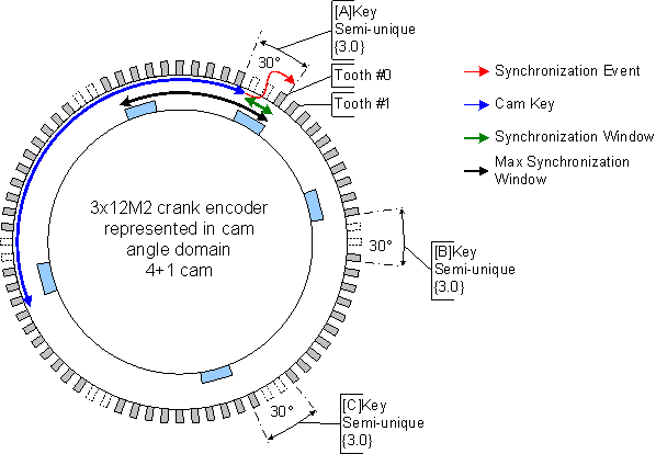
The window allows ratification of the synchronizing event. The maximum synchronization window annotation describes the worst case window where a synchronization event could occur for this 3x12M2 pattern. The window is measured back from the missing tooth key and has units of teeth. For the 3x12M2 wheel the maximum synchronization window value is 10. No more than 9 teeth should ever be observed between observing the synchronization event and observing the semi-unique key. However, this particular setup happens to have the key event on the synchronizing source (4+1) occurring within the missing tooth region and so the window could be reduced to 0 for this example. Events that fall outside the specified window are ignored.
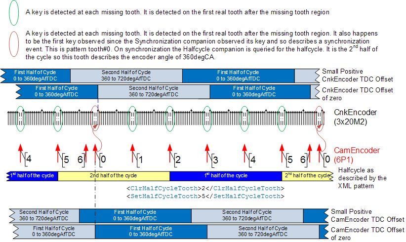
The figure illustrates the "critical edge" events associated with a 3x20M2 crank encoder that is used in conjunction with a 6 plus 1 tooth cam encoder that provides half cycle information and synchronization information. The synchronization window should be configured as zero because the cam's key is detected in the crank encoder's missing tooth region (which is the crank's key). The halfcycle window should also be set to zero. This is because the cam synchronizes the crank encoder and thus the halfcycle state will always be known when the crank encoder is synchronized.
Executing the motohawk_flexencoder_project script with an encoder_system_type of 'Cnk_3x20M2_Cam_6P1' will create a sample project of this example.
The absolute source encoder pattern for some encoder systems has semi-unique keys that represent engine TDCs. A 4 tooth encoder (4X) used in a 4-stroke application has one tooth per TDC when in use with an 8 cylinder application. Each tooth is a semi-unique key on such an encoder. Without a synchronization companion the absolute source could guess what key represents TDC#1 since each key is known to be a TDC. The system may just assume that the next observed key represents TDC#1 and force synchronization. The ignition and fuelling system must be capable of allowing the synchronization to be guessed like this and the absolute source must have the same number of keys as there are TDCs else the guess could be wildly incorrect. That is the engine system must support distributed ignition (or not control ignition), banked fuelling (or not control fuelling) and have the same number of TDCs as there are semi-unique keys before this approach could be used. The Allow TDC Sync on Loss (of Sync Companion) check box enables this option. If the synchronization companion were to be diagnosed as having failed (typically a loss fault) and the absolute source has not yet synchronized then synchronization would be forced to occur on the first key observed after the failure had been flagged when this attribute is checked.
Because only very specific engine management systems should use this option an additional Support TDC Sync on Loss (of Sync Companion) option check box must also be checked to expose the feature. This gives the application developer the capability to remove the possibility of inadvertantly enabling this feature via calibration.
A halfcycle companion is an encoder source that can be used by another absolute source to determine halfcycle information. An absolute source that has Num Revs Per Cycle set to 2 will require a halfcycle companion if that encoder source is going to be able to automatically discern what revolution the source is currently operating in. In the most common setup the crank encoder source is an absolute source that monitors position from the flywheel. It would reference the cam encoder source that is monitoring cam position via its Name of Halfcycle Companion to discern which revolution in the engine cycle the crank encoder source had just observed.
All sources that utilize a halfcycle companion will need to configure the halfcycle window. Incorrect configuration can lead to rogue halfcycle faults.
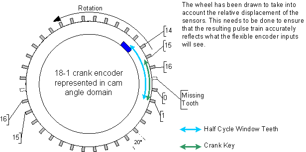
The example above has an arbitrary crank key defined that identifies tooth #1 on the crank wheel. The cam tooth is an edge key (every observed tooth of an edge key is considered to be a key) and as such needs to be looked for in a window. The pattern's HalfcycleEncoding would have been configured for window. The halfcycle window occurs between crank tooth #13 and crank tooth#1. If at least 5 crank teeth have been observed prior to observing the crank key then the encoder source can infer that the cam tooth would have occurred if it was going to occur. Note that the crankshaft revolves twice for one camshaft revolution and so every second key will occur without the cam tooth occurring. The encoder source thus infers the halfcycle by looking for the presence or absence of the cam tooth within this window. Configure the window to be too small and the encoder will look in the wrong region and incorrectly assume the halfcycle state that is applicable when the cam tooth is not observed. Configure the window too large and the encoder startup performance is compromised because all the window teeth need to be observed before halfcycle determination can occur.
An encoder that needs to use a companion that is employing HalfcycleEncoding=window should only have a single unique key defined. To define more will confuse the implementation because it does not associate the window to a specific key.
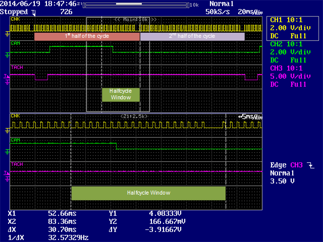
The figure below was created by monitoring with a scope the model created by the motohawk_flexencoder_project script with an encoder_system_type of 'Cnk_60M2_Cam_Tooth'. A halfcycle window of 20 encapsulates the falling edge of the cam tooth. The companion encoder created on the cam (CamEncoder) has a falling synchronous edge. A bad halfcycle window error would result if the cam had been configured for a rising synchronous edge. The first tooth after the missing tooth region is tooth#0 for this pattern. Observing a cam tooth before the key on the crank encoder "tells" the encoder system that the next halfcycle is the 2nd half.
The halfcycle window is still important for start-up performance. Here the window defines how many source teeth on the crank (normally) need to be observed before the source can either guess the halfcycle state or know that the halfcycle companion will have synchronized. An encoder using state based halfcycle encoding will always guess the first halfcycle if the companion has not yet synchronized. Appropriate definition of the halfcycle window and the ClrHalfCycleTooth and SetHalfCycleTooth can allow optimal synchronization.
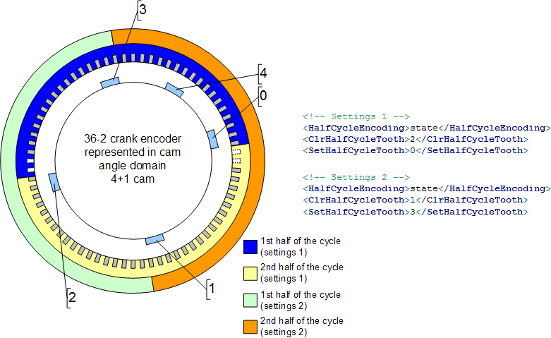
Consider the example wheel, which is a 36M2 crank encoder combined with a 4 plus 1 tooth cam encoder. The cam has a key with a ratio of 0.5 at tooth#4 (period from 3 to 4 divided by period from 2 to 3) and a ratio of 1.0 at tooth#0 (period from 4 to 0 divided by period from 3 to 4). The halfcycle window is 35 crank teeth. It is measured from the crank key at the missing tooth back to cam tooth#2. Cam tooth#2 is referenced because it needs to be seen before the ratio at cam tooth#4 could be calculated.
The example illustrates two valid sets of values for ClrHalfCycleTooth and SetHalfCycleTooth. The tuning halfcycle section provides some further detail on selecting values for these attributes.
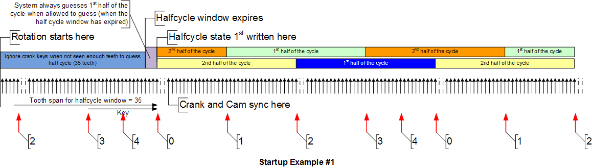
The first missing tooth key on the crank in Startup Example #1 is ignored because the halfcycle window has not yet expired. By the time the second missing tooth region is observed the halfcycle window has expired and the cam has also synchronized. Thus the system does not need to guess the halfcycle and the correct state is applied.
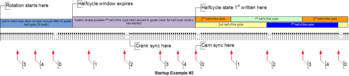
In Startup Example #2 the first missing tooth key on the crank is still ignored because the halfcycle window has not yet expired. No key is detected the first time cam tooth#0 is observed because it can't be detected without first observing cam tooth#2. Crank encoder synchronization occurs at the second missing tooth because the halfcycle window has expired. The halfcycle state is guessed to be the first half of the cycle because the cam has not yet synchronized. This guess won't result in a halfcycle error when the cam does synchronize if ClrHalfCycleTooth and SetHalfCycleTooth are selected such that the 2nd halfcycle is associated with the cam's key. For example, a SetHalfCycleTooth value of 0 along with a ClrHalfCycleTooth value of 2 implies that the system is in the 2nd half of the cycle when either cam tooth#0 or cam tooth#1 is observed and in the first half of the cycle when cam tooth#2, cam tooth#3 or cam tooth#4 is observed. Therefore the half cycle will always be the 2nd half of the cycle when cam tooth#0 is observed.
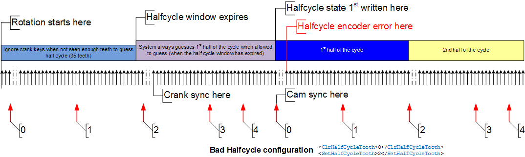
The bad halfcycle configuration example illustrates how a halfcycle error can occur if ClrHalfCycleTooth and SetHalfCycleTooth are not set correctly. The error results because the halfcycle state is set to the first halfcycle when cam tooth#0 is observed, but in the previous halfcycle it was guessed to also be the 1st halfcycle. The halfcycle state did not alternate between 1st halfcycle and 2nd halfcycle and so an encoder error resulted.
A developer has a few options available to them that will allow a single executable to support a variety of different encoder system configurations by altering some calibrations.
Use the calibration associated with the Halfcycle Companion In Use attribute to manipulate whether the encoder system should attempt to discern halfcycle information from the named source (typically the cam). Thus this value would be set to true when the cam was to be connected and false otherwise. An executable that is to support both a cam and camless encoder system will also need to configure the encoder source that describes the cam to indicate whether the source is to be considered by the encoder system. Use the calibration associated with the Create Source attribute of this cam encoder source to define whether the resource should be created. Set to false when there is no cam encoder source to be connected. This will prevent errors associated with the cam (like Loss) from being detected by the encoder system and flagged to the application. Set to true when the cam encoder source is to be considered.
An absolute encoder source will not function if its Halfcycle Companion In Use attribute is true, but the calibration associated with Create Source attribute is false. This is because one source is indicating that it needs information from the other source and yet that source is indicating that it is not to be created. The failure may manifest as Encoder State reporting a zero (Not Created) or the Encoder System may fail to switch to that source (the ActiveSource won't reflect the requested Source) because it is not considered legal.
Only some encoder patterns require a synchronization source, which means that supporting an optional synchronization source can be quite common place since the Pattern Selector allows the pattern for an encoder source to be altered.
The approach to supporting such a system is identical to the approach described to Support a Cam and Camless System from a Single Executable except the calibration associated with the Sync Companion In Use attribute would be used to configure whether the synchronizating source is to be used by a particular setup.
An encoder system that consists of a high-resolution crank encoder source with a low resolution cam encoder source and a crank synchronizing source is often referred to as a 3-source configuration. The high-resolution crank encoder source may be a 151 equidistant tooth wheel that rotates twice per cycle. The cam might be single tooth that rotates once per cycle and the crank synchronizing source might also be a single tooth, but it rotates twice per cycle (thus providing synchronization information for the high-resolution crank source).
A slight variation on the 3-source configuration described above is a 2-source configuration where the cam encoder is used to provide both the halfcycle information and the synchronization information. The previously described methods won't work in this situation because they work by disabling whether a source is to be used. Here the crank encoder's sync companion needs to be mapped between the cam encoder or the synchronizing encoder based upon whether a 3-source or 2-source configuration is to be used.
Check the Allow companions that are connected to this source to be calibrated option to allow a single executable to utilize both configurations. The connections used are defined via the calibrations associated with the Name of Halfcycle Companion and Name of Sync Companion attributes.
The Allow companions that are connected to this source to be calibrated option will utilizes more resources than a setup that does not require such flexibility.
The Allow companions that are connected to this source to be calibrated option can also be used to implement a system with a optional synchronizing source from a Single Executable and/or support a Cam and Camless System from a Single Executable.
The sources referenced by the calibrations associated with the Name of Halfcycle Companion and Name of Sync Companion attributes still need to be created. The absolute encoder source will not function if the source referenced by the Name of Halfcycle Companion or Name of Sync Companion are not created (Create Source attribute). This is because one source is indicating that it needs information from the other source and yet that source is indicating that it is not to be created. The failure may manifest as Encoder State reporting a zero (Not Created) or the Encoder System may fail to switch to that source (the ActiveSource won't reflect the requested Source) because it is not considered legal.
The motohawk_flexencoder_project script when used with the 'FlexCal' encoder_system_type demonstrates this configuration.
There can be occasions where it is beneficial to ignore the halfcycle state being reported by the companion. See the Ignore Halfcycle Companion option of the Set Source Info block for further details.
| Copyright 2010-2018 Woodward Corporation. All Rights Reserved. | Visit Us: mcs.woodward.com |