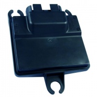
24-pin Module Family
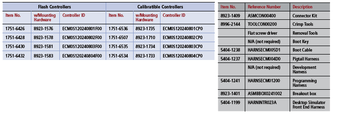
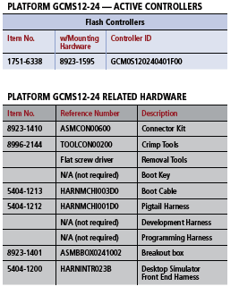
See Product Guide for Active Part Numbers and Related Hardware (Connectors, Harnesses, Tools).
ECM-0S12-024 (obsolete)
Hardware Features
- Microprocessor: MC9S12DT128, 24MHz
- Memory: (MC9S12DT128BMPV) 128 K Flash, 8K RAM
- Operating Voltage: 8-20VDC
- Operating Temperature: -40 to 105 C
- Sealed Connectors Operable to 10ft submerged
Inputs
- Up to 11 Analog Inputs
- 1 VR Frequency Input
Outputs
- 3 TTL Level Ignition System Outputs
- 2 10A Low Side PWMs
- 1 1.0A Tachometer Output
- 1 5A H-Bridge PWM
Datalinks
- 1 CAN 2.0B Channel
- Note: 1Mbps is not supported on the S12 modules.
Fixed Point Procesor
The Processor is a Fixed Point processor. Although floating point emulation is possible, it is very resource intensive and should be avoided. Model should be designed using Fixed Point.
Code Warrior H12 Pro Ed C 4.6 Compiler required
City IDs
The ECM-0S12-024 default City ID is 0x81 except the 0804 version which has City ID 0x0B.
Bootstrap
The ECM-0S12-024 can be forced to remain in the firmware bootloader by applying a bootstrap sequence. The bootstrap sequence is:
| Pin | State for Boot |
|---|---|
| AN1M | |
| AN2M | |
| AN3M | High |
| AN4M | High |
| AN5M | Low |
| AN6M | High |
| AN7M | High |
| AN8M | Low |
Variations and Replacement Part Numbers
The ECM-0S12-024-0502 was updated to the ECM-0S12-024-0802, but has the same functionality as described in the -0502 datasheet.
The ECM-0S12-024-0503 has been updated to ECM-0S12-024-0801 [and ECM-0S12-024-0804 (different hardboot loader)], but has the same functionality as described in the -0503 datasheet.
The -0503 (0801/0804) is a variation of the 0502 (-0802) with different pullup/pull down combinations for the analog ins and three EST’s replaced by more analog ins.
All ECM-0S12-024 are now obsolete from FEB-2023!
BUY NOW
8923-1583 ECM-0S12-024-0804 PROD with mounting hardware.
GCM-0S12-024
Hardware Features
- Microprocessor: MC9S12DT128, 24MHz
- Memory: (MC9S12DT128BMPV) 128K Flash, 8K RAM, 2K EEPROM
- Operating Voltage: 8-16VDC
- Operating Temperature: -40 to 105 C
- Sealed Connectors Operable to 10ft submerged
Inputs
- 6 Analog Inputs
- 4 Discrete Inputs
Outputs
- 4 1.5A Low Side PWMs
- Multi-function ESTOP (Detect/Assert)
- Optional 0-12V LSO (Easy Link Interface)
Datalinks 2 CAN 2.0B Channel
- Note 1Mbps is not supported on the S12 modules
Part Numbers
Compiler
The Processor is a Fixed Point processor.
Code Warrior H12 Pro Ed C Compiler required
City ID: GCM-0S12-024 default city ID is 0x91.
GCM-OS12-24 Target Definition
There is only one Target for the GCM-OS12-024 modules. This is the GCM-0S12-024-0401. You can use this target to build for the other GCM-0S12-24-0402 and -0403 modules. MotoTune will give a warning, but press OK to continue. The difference between the modules are the pullup/pulldown valuse shown below.
GCM-0S12-024-0401-F00 (MCHI0401)
AN1 -- 220.k PD
AN2 -- 220.k PD
AN3 -- 220.k PD
AN4 -- 220.k PD
AN5 -- 220.k PD
AN6 -- 220.k PD
GCM-0S12-024-0402-F00 (MSIM0401)
AN1 -- 51.1k PU
AN2 -- 1.00k PU
AN3 -- 180. PU
AN4 -- 220.k PD
AN5 -- 180. PU
AN6 -- 1.00k PU
GCM-0S12-024-0403-F00 (SMUX0401)
AN1 -- 1.00k PU
AN2 -- 1.00k PU
AN3 -- 1.00k PU
AN4 -- 1.00k PU
AN5 -- 1.00k PU
AN6 -- 1.00k PU
BUY NOW
8923-1596 GCM-0S12-024-0401-F PROD with mounting hardware.
Bootstrap
The GCM-0S12-024 can be forced to remain in the firmware bootloader by applying a bootstrap sequence. The bootstrap sequence is:
| Pin | State for Boot |
|---|---|
| AN1M | High |
| AN2M | High |
| AN3M | Low |
| AN4M | High |
| AN5M | High |
| AN6M | Low |
| AN7M | |
| AN8M |
Frequently Asked Questions/Topics
PWM and Frequency Resolution
The 24-pin module has limited PWM and frequency input resolution due to the registers – 16 bit or 8 bit, as compared to 32 bit on other MCS PowerPC modules. The clock rate also limits this resolution. The frequency will be traded off for duty cycle resolution, and frequency range is limited. PWM over a large frequency range is not possible.
The PWM outputs on S12 modules are very sensitive to the minimum and maximum frequency settings in the model since there are limited clock resources that are shared between the PWMs, so set your minimum and maximum to reasonable numbers for your system. The output is optimized by the minimum and maximum frequency range settings in the PWM or frequency input block. They must be set as narrowly as possible, so select maximum frequency checkbox and make sure to put in your upper frequency limit.
Using 16-bit PWM or frequency input resources provides some additional resolution over the 8-bit.
Check the module cross reference page to see which outputs have the capability of using a 16-bit resolution resource.
Is there a pin removal tool for the 24-pin module? No, there isn't a pin removal tool for these modules. If you remove the snap-on end, the pins can be removed by deflecting the white tabs. You’d just need a flat screwdriver.
Can I run the 24-pin modules at 1Mbps? No, the S12 modules do not support CAN at 1Mbps. The option will be removed from the CAN dropdown in a future release to reflect this limitation.


