70-pin Module Family
Contents
- 1 ECM-5642A-70
- 2 ECM-S12X-70
- 3 Product Summary
- 4 Datasheets
- 5 Part Numbers
- 6 Compiler
- 7 Fixed Point
- 8 Memory Use
- 9 MC33810 Current Control and Diagnostics
- 10 Frequently Asked Questions/Topics
- 10.1 PWM and Frequency Resolution
- 10.2 How is the CAM pullup used?
- 10.3 When I build a MotoHawk Project, I get a build error: ERROR L1102: Out of allocation space in segment RAM_BLOCK0_SEG at address 0x3D46
- 10.4 Does the 70-pin module fault status report short vs open fault states?
- 10.5 How Do I recover the 70-pin module?
- 10.6 Is there an available ECU Side connector?
ECM-5642A-70
ECM-S12X-70
See Product Guide for Active Part Numbers and Related Item Information (Harnesses, Connectors, ..)
Hardware Features
- 70-Pin platform
- Microprocessor: Freescale S12XE, 50MHz
- Memory: 256K Flash, 16K RAM, 4K Internal
- EEPROM, 64K serial FRAM
- Calibratible Memory: 1M Flash, 64K RAM Note: only 13k is available to the application.
- Operating Voltage: 6.5-16 Vdc, 24 V (Jump Start), 5V (Crank)
- Operating Temperature: -40 to +85 ºC
- (105 ºC possible in some applications)
Inputs
- VR or digital crank position sensor
- Digital cam position sensor
- 17 analog
- 1 oxygen sensor
- 4 switch
- 1 speed
- 1 emergency stop
Outputs
- 4 injector (high impedance) drivers
- 3 ignition coil drivers
- 1 tachometer driver
- 9 low-side drivers
- 1 main power relay driver
- 2 sensor supply (5V) outputs
Datalinks
- 2 CAN 2.0B Channels
- 1 RS485 Channel
Product Summary
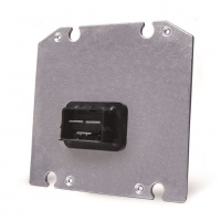
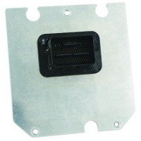
The ECM-S12X-070 family of engine control modules are rugged controllers capable of operating in harsh automotive, marine, and off-highway applications. The module and its connector system are environmentally sealed and suitable for engine mounting in many applications.
This unit provides 70 connector pins with inputs, outputs, and communication interfaces that support a wide variety of applications. The ECM-S12X-070 is part of the MotoHawk Control Solutions ControlCore® family of embedded control solutions. The ControlCore operating system, MotoHawk® code generation product, and MotoHawk’s suite of development tools enable rapid development of complex control systems.
Each controller is available in ‘F’ (Flash) or ‘C’ (Calibratible) versions. Flash modules are typically used for production purposes. Calibratible modules are typically for prototyping/development only; they can be calibrated in real time using MotoTune®.
IMPORTANT! Woodward does not warranty this ECM based on information supplied in this article, but only with an expressed and specific productionsupply agreement based on customer’s operating mode. Information in this article is subject to change without prior notice. Please contact Woodward sales for more information.
Datasheets
ECM-S12X-070 Family Engine Control Modules Product Information Sheet (36348)
ECM-0S12-070-1001 Datasheet (36347)
Part Numbers
Note: Parts 1751-6458 and 8923-1620 are INACTIVE since Jan 2012.
BUY NOW
8923-1640 ECM-S12X-070-1001 DEV with mounting hardware
8923-1761 Connector kit for ECM70
5404-1141 Pigtail harness for ECM70
Compiler
Codewarrior 4.6 by Freescale is required for the module.
Fixed Point
The 70-pin module uses the Freescale S12X processor which is a fixed point processor. Although floating point emulation is possible, it is extremely resource intensive and use of floating point should be avoided. The application should be devloped using fixed point.
For more information, see MotoHawk Fixed-Point and B-Numbers.
Memory Use
Memory use on the S12's is different than on the Power PC modules.
RAM
Both the ECM-S12X-70-1001 and ECM-S12X-70-1002 have approximatly 13k RAM avaialble to the application. This is as:
- ~8k Non-Paged RAM
- ~4k Paged RAM
- ~ 1k EEPROM RAM Overlay.
The ECM-S12X-70-1002 has an additional 16k of Calibration/RAM that can be shared between calibration memory or general purpose RAM. So, if calibration is 8k, then an additional 8k is then available for general purpose RAM.
FLASH
The flash in the ECM-S12X-70 is in 16k pages. This means that each 'chunk' of code must fit into 16k.
Therefore, it may be needed to break large subsystems up into smaller subsystems, to fit within the 16k page.
MC33810 Current Control and Diagnostics
The Spark Outputs (MotoHawk resource EST1,2,3), LSO1, LSO3,4,5,8 use the MC33810 IC as the driver. See MC33810 for additional help on current control and diagnostics available through the MotoHawk MC33810 blocks.
The control and diagnostics available with the MC33810 will depend on the type of channel the output is connected to. The following are connected to channel types: IBGT type Pre-Gate Drivers (IGBT Type): EST1, EST2, EST3 MOSFET type GPGD Pre-Gate Driver: LSO1 General Gate Driver (Out Type): LSO, 3,4,5,8
The IBGT type pre-drivers share a common channel for diagnostics. Typically, each driver is connected to spark coils and so this shared arrangement does not present an issue because the channels (predominantly) don’t overlap. Diagnostics may be impacted if the spark pins (EST1, 2, 3) are driven by an output so that the output on conditions overlap.
Open load fault detection is not available on EST1, EST2, and EST3 unless they are driven by a One-Shot or PSP type (ex spark sequence, Dual PSP, Multiple PSP) output.
The remaining LSO's do not use the MC33810 as the driver, but instead use the NCV751. There is not a specific blockset for this driver. Fault reporting is via the IO Fault Status Block.
Frequently Asked Questions/Topics
PWM and Frequency Resolution
The 70-pin module has limited PWM and frequency input resolution due to the registers – 16 bit or 8 bit, as compared to 32 bit on other MCS PowerPC modules. The clock rate also limits this resolution (1MHz). The frequency will be traded off for duty cycle resolution, and frequency range is limited. PWM over a large frequency range is not possible.
The PWM outputs on S12 modules are very sensitive to the minimum and maximum frequency settings in the model since there are limited clock resources that are shared between the PWMs, so set your minimum and maximum to reasonable numbers for your system. The output is optimized by the minimum and maximum frequency range settings in the PWM or frequency input block. They must be set as narrowly as possible, so select maximum frequency checkbox and make sure to put in your upper frequency limit.
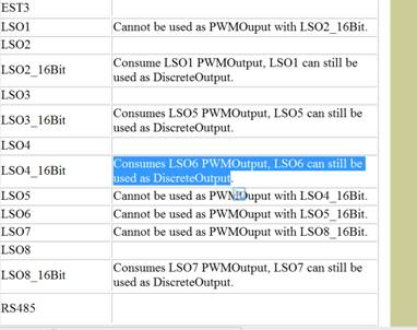
Using 16-bit PWM or frequency input resources provides some additional resolution over the 8-bit, however using the 16-bit PWM on the 70-pin will also consume other pins.
How is the CAM pullup used?
In order to use CAMDG (30) as a freq input and software select on the 1k pullup to 5V, you should use a MotoHawk Discrete Output block and select the "en_campu" resource. Supplying a positive value to the discrete output block will activate the pullup to 5V.
When I build a MotoHawk Project, I get a build error: ERROR L1102: Out of allocation space in segment RAM_BLOCK0_SEG at address 0x3D46
When buidling a model with a S12 target, the orginal settings of the stack in the target definition need to be changed. A good starting point for stack and heap sizes on S12 modules is 512 bytes for each. The heap size does not have the same restriction as the MPC5xx based modules and thus does not have to be a multiple of 2K. The 70-pin module has a total of 8K of RAM, which is used stacks, heap, and various other things.
Does the 70-pin module fault status report short vs open fault states?
No, only the presence or absence of a fault is reported.
How Do I recover the 70-pin module?
The 70-pin module does not use the boot key. Instead, it uses a boot harness which is part number 5404-1144. The boot harness puts a series of 5V or 0V inputs to the analog inputs of the module which is recongized by the bootloader.
See Boot Key Recovery article for more information.
Is there an available ECU Side connector?
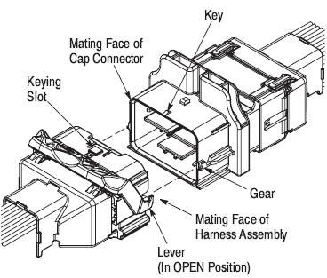
TE Connectivity, formerly known as Tyco Electronics Ltd, provides an inline male side mating connector which will mate to Woodward part number 1635-1772. The TE Connectivity part number is 1438726-1. More information can be found on the TE Connectivity website.


