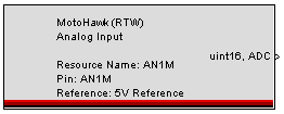
MotoHawk:Blocks:Analog Input
Analog Input
This MotoHawk block provides access to the value of the A/D converter channel associated with the selected resource (pin). The output value is the width of the selected type and represents the ratio of the voltage level of the analog resource to the Reference Voltage (usually 5V), as seen by the controller chip(s).
Block ID
motohawk_ain
Library
MotoHawk_lib/Analog I/O Blocks
Description
In most cases, there are voltage divider and shifter circuits on the target module that map the voltage being measured into the range that the controller chip(s) can measure, usually 0 to 5 Volts. The resolution at which this resulting voltage can be measured depends on the controller chip, usually 10 or 12 bits (1023 or 4095 maximum value, respectively). A reading of zero represents the minimum voltage specified for these external circuits and a maximum value represents the highest specified voltage.
For example, if the specified range of the external circuits were -5 to +10 Volts, and 10 is selected for the Output Width in Bits parameter, a value of zero would represent -5V, a value of 1023 would represent +10V and a value of 341 would represent 0V
( (0V - -5V) * 1023 / (10V - -5V) = 5*1023/15 ).
You can adjust the range of the number output by this block by using the Output Width in Bits parameter. The hardware will be configured to meet the request as closely as possible. Actual hardware configurations vary from module to module. The readings will fill this range, regardless of the resolution of the controller, and are always positive. See examples below:
| ADC Configured Resolution (bits) | Scale (bits) | Raw ADC | Raw ADC (binary) | Scaled ADC | Scaled ADC (binary) |
| 10 | 11 | 513 | 1000000001 | 1026 | 10000000010 |
| 10 | 13 | 513 | 1000000001 | 4104 | 1000000001000 |
| 12 | 11 | 789 | 1100010101 | 394 | 110001010 |
| 8 | 7 | 250 | 11111010 | 125 | 1111101 |
Zeros added for padding are highlighted in red.
Block Parameters
| Parameter Field | Values | Comments/Description |
| Resource Name | Alpha-numeric text, single-quote enclosed | Name as displayed in block. No special characters, such as spaces, dashes, commas (underscore allowed). Select a unique name. If none is given, the name inherits from the pin name, or the listed Vardec name if the I/O pin calibrated from MotoTune option is selected. |
| Resource | Drop-down list | Assign analog input resource. The list varies per module. |
| Reference | 5V/2.7V | Select Reference voltage level for selected input. This is supported by the ECM-563, GCM-563, and HCM-563 targets. This parameter is ignored if not implemented for the current target module. |
| Data Type | Drop-down list | Assign Data Type: int8, uint8, uint16, etc. |
| Output Width in Bits | 7-16 | Specify the number of bits used to represent the output value. Ensure that this fits within the range of the Data Type selected (e.g., 7 for int8, avoiding the sign bit). |
| Output creation status | Check box (enable) | Enabling "Output Creation Status" adds an optional uint16 output that provides the ControlCore error status. 0 means OK, and any other number is an error. This can be useful for disabling diagnostics or strategies based on different I/O calibrations. (Please type 'help motohawk_enum_error' in Matlab Command Window, for more information.) |
| Allow I/O pin to be calibrated from MotoTune | Check box (enable) | Name, Access Levels and MotoTune Group Strings fields are available |
| Vardec Name | Alpha-numeric text, single-quote enclosed | Name as displayed in MotoTune, for variable. No special characters, such as spaces, dashes, commas (underscore allowed). |
| Read Access Level | 1-4 | Sets security level 1 lowest, 4 highest, for user access to read value |
| Write Access Level | 1-4 | Sets security level 1 lowest, 4 highest, for user access to write value |
| MotoTune Group String | Alpha-numeric text | Determines Folder name and hierarchy as displayed in MotoTune. Use "|" character between folder names to delineate subfolder structure. |
