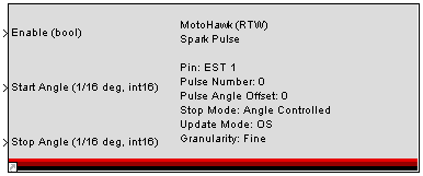
MotoHawk:Blocks:EST Sequence Out
EST Sequence Out
This MotoHawk™ block defines the Electronic Spark Timing (EST) sequence for a selected resource.
Block ID
motohawk_seq_out_est
Library
MotoHawk_lib/Advanced Digital I/O
Description
This MotoHawk™ block generates a series of pulses, starting at a given encoder crank angle, and either stopping at an angle or after a certain duration. Stop Mode parameter selects which strategy to use.
Two of these blocks may be used on a single EST resource, to generate interleaved pulses, sharing a single pin. Each block must identify the pulse number (0 or 1). If no interleaving is needed, simply use pulse number 0.
Pulse Angle Offset is used to apply a fixed offset to the given pulse, relative to TDC. The start and stop angles are then relative to this offset.
The Update Mode selects whether the OS should protect against missing pulses and double pulse generation. If Application is selected, no error checking is provided, and the application is completely trusted. If OS is selected, some amount of checking is done by the OS.
Set the Enable input True to generate a pulse as configured.
Angle inputs are before TDC (BfTDC), in units of 1/16th of degree crank angle. Time inputs are in microseconds. Eg: 730degBfTCD == 10degBfTDC == -710degBfTDC
Angles are converted internally to Mod(angle, DegInCycle). It is therefore not possible to schedule a pulse more than one cycle into the future. When Mod(start - stop,DegInCycle) == 0, angular duration is considered to be zero. For example, this will occur on a 4-stroke when start = 720, stop = 0. To achieve a maximum angle, stop = start - DegInCycle - 1/16.
Block Parameters
| Parameter Field | Values | Comments/Description |
|---|---|---|
| Resource | Drop-down list | Select from available listings, as appropriate, to apply output. |
| Pulse Number | 0, 1 | Set as needed if using interleaved pulses (two pulse blocks feeding the same resource). One pulse block would be set to 0, the other, to 1. |
| Pulse Angle Offset (deg) | Numeric | Enter value for degree of angle offset from TDC |
| Stop Mode | Select method for Stop | |
| Angle Controlled | Control Stop Mode by Angle | |
| Duration Controlled | Control Stop Mode by Time Duration | |
| Update Mode | OS/Application | Select OS to have the system update for errors. Select Application to allow the application to run without updates. |
| Granularity | Select granularity (resolution) as required - fine takes more processing time. | |
| Fine | Interpolates engine position between encoder teeth. Additional calculations result in reduced maximum duty cycle. | |
| Coarse | No interpolation, uses encoder teeth to identify engine position. | |
| Input Max Duration Port | Check box (enable) | Select to deploy input to control Maximum duration or port output |
| Minimum Duration Mode | Select whether to have static or dynamic duration | |
| Static | Select to have constant value, input in mask | |
| Dynamic | Select to have value calculated in model, input into block. | |
| Minimum Duration (ms) | Numeric | Enter value for injector duration (if Static Duration Mode selected). |
