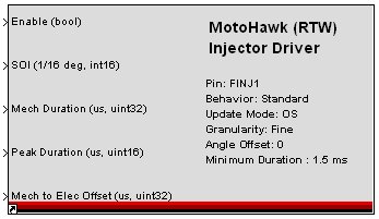
MotoHawk:Blocks:Injector Driver
Fuel Injector Output
This MotoHawk™ block is intended to be a fuel injector driver.
Block ID
motohawk_injector
Library
MotoHawk_lib/Advanced Digital I/O
Description
Two selectable operating modes (Behavior) are available, Standard and Transient.
In Standard mode, a single pulse is generated per cylinder top-dead-center (TDC), with an electrical duration of 'Mech Duration' plus 'Mech to Elec Offset', and starting at a crank angle of start-of -injection (SOI) plus an 'Angle Offset'.
In Transient mode, up to two pulses are generated. The first pulse is started at SOI, and if the the desired duration rises above the 'Make-Up Min Mech Duration' after the pulse has completed, then a second Make-Up pulse will be generated, ending at Make-Up EOI (end-of -injection).
'Angle Offset' is normally the crank angle for the given physical cylinder, in degrees after TDC of cylinder 1.
'Peak Duration' is used with a Low-Impedance Injector, and controls the duration of the peak portion of the pulse. The remaining time is the hold time.
The Update Mode selects whether the OS should protect against missing pulses and double pulse generation. If Application is selected, no error checking is provided, and the application is completely trusted. If OS is selected, some amount of checking is done by the OS.
Pulses are only generated while the Enable input is True. When the Enable input goes False, any pulses already started will complete.
Block Parameters
| Parameter Field | Values | Comments/Description |
|---|---|---|
| Resource | Drop-down list | Select from available listings, as appropriate, to apply output. |
| Behavior | Select operating mode for output | |
| Standard | A single pulse is generated per cylinder TDC, with an electrical duration of Mech Duration (per input of that name) plus Mech to Elec Offset (per input of that name), and starting at a crank angle of SOI (per input of that name) plus Angle Offset value as entered. | |
| Transient | Up to two pulses are generated. The first pulse is started at SOI, and if the the desired duration rises above the Make-Up Min Mech Duration after the pulse has completed, then a second Make-Up pulse will be generated, ending at Make-Up EOI. If the first pulse has already extended beyond 'Make-Up EOI', the make-up pulse will not be generated. When using the Transient mode, there must be a separation between the EOI and next SOI that is larger than one crank encoder tooth. Enter an appropriate angle into Min EOI to SOI Angle. | |
| Update Mode | Select whether to have OS protect against pulse errors. | |
| OS | Operating System protects against missing pulses and double pulse generation. | |
| Application | No error checking is provided, and the application is completely trusted. | |
| Granularity | Fine or Course | Fine granularity (resolution) interpolates engine position between encoder teeth. Can result in reduced maximum duty cycle for MPC5xx based modules. Course granularity does not use interpolation. Angles resolve to the closest encoder tooth. Modules besides those cores that have an MPC5xx ignore this setting and utilize fine granularity irrespective of this setting. |
| Angle Offset (deg aTDC) | Numeric | Enter angle offset value from TDC for SOI. |
| Use Make-Up EOI Port | Check box (enable) | Enable control of EOI via port instead of via Min EOI to SOI Angle parameter. Useful for Transient Behavior mode (see above). |
| Min EOI to SOI Angle (deg) | Numeric | Enter minimum angle from EOI to SOI. |
| Minimum Duration Mode | Static or Dynamic | Only applicable to MPC5xx based modules. Any scheduled electrical injector duration smaller than this value is considered to have zero duration when scheduled. Is a member of the mask when the static Minimum Duration Mode is selected and is a signal when dynamic is selected. |
| Minimum Duration (ms) | Numeric | Enter value for injector duration. Only applicable if a Static Minimum Duration Mode was selected. |
| Output Injector Diagnostics | Check box (enable) | Enable diagnostic output ports on block, including Transition Count, and Transition Time. |
| Allow I/O pin to be calibrated from MotoTune | Check box | Name, Access Levels and MotoTune Group Strings fields available |
| Name |
Alpha-numeric text, single-quote enclosed
|
Choose the Name to reference. No special characters, such as spaces, dashes, commas (underscore allowed). |
| Read Access Level | 1-4 | Sets security level 1 lowest, 4 highest, for user access to read value |
| Write Access Level | 1-4 | Sets security level 1 lowest, 4 highest, for user access to write value |
| MotoTune Group String | Alpha-numeric text, single-quote enclosed | Determines Folder name and hierarchy as displayed in MotoTune. Use "|" character between folder names to delineate subfolder structure |
