MotoHawk Blocks:Module Configuration Blocks:Peak/Hold with Off Time (PHWOT) Controller
Contents
Peak/Hold Controller
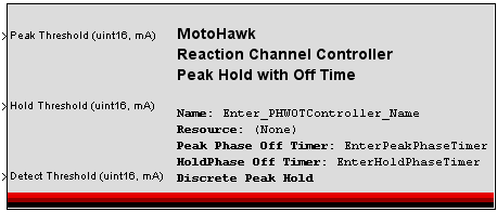
This MotoHawk™ block defines a Peak/Hold Reaction Channel controller. Reaction Channel controllers are used to control circuits that utilizes the microcontroller's Reaction Module so that they can perform load current modulation. When the modulation should occur is controlled by an independent block like a PWM. A single Reaction Module block plus a Reaction Module Off Time block will also need to exist in the model in order to fully define the controller. A Reaction PH Channel definition block would also need to exist to expose the defined controller on an output. This controller can also be used to drive loads that don't require load current modulation (a high impedance load for example).
Block ID
React PH Controller
Library
MotoHawk_lib/ModuleConfiguration
Description
- Signal Descriptions
- Block Mask Parameter Descriptions
- Circuit Operation
- Fault Behavior
Circuit Principles
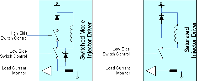
The Peak/Hold with Off Time (PHWOT) reaction channel controller is intended for use with a circuit topology like the ones illustrated below.
The switched mode driver has a high side switch that is turned ON whilst the actuator is ON and the low side switch runs a high frequency PWM that will modulate the load current. The circuit is only able to sample load current while the low side switch is ON. Thus the OFF time needs to be an open loop parameter that switches the low side switch OFF for a set amount of time each time the low side current attains the specified current threshold. The PHWOT behavior supports a peak and a hold phase. Nominally the [#peakthreshold current] threshold during peak is higher than what is used during the hold phase.
A high impedance load could be driven with either circuit. Typically the [#peakthreshold peak current] and the [#holdthreshold hold current] thresholds are set to values that won't be attained by the load and as such no modulation will occur.
Peak/Hold Operation
Operation
This circuit behavior supports a peak phase and a hold phase. When [#usetimedpeakhold timed peak/hold is in use] the time spent in peak is controlled by the referenced [TimedPeakHold.html Timed Peak/Hold] block. Note that the time spent in peak refers to the time spent controlling to the peak threshold once the peak threshold has been attained. If discrete peak/hold is in use then the appropriate mode is defined by the state currently specified by the [DiscretePeakHold.html Discrete Peak/Hold] block.
Preventing Timer Allocation Errors
[ReactionChannelStatus.html#timerallocationerror Timer Allocation Errors] can result when using the PHWOT Reaction Channel controller with [#usetimedpeakhold timed peak/hold]. These errors are not driver faults, but setup errors that are reported via the [ReactionChannelStatus.html Reaction Channel Status] block.
The reaction module supports a pool of internal timers that are shared by all of the reaction channels and is of a finite size. For example MPC564x cores support only 3 timers in this pool. A PHWOT Reaction Channel that is implementing Timed Peak needs to be able to acquire one of these timers. A [ReactionChannelStatus.html#timerallocationerror Timer Allocation Error] will result if too many PHWOT Reaction Channels implementing Timed Peak assert at the same time since they each will require their own timer, which the underlying silicon can't provide. Other Reaction Channel behaviors may also draw upon these timers and would need to be considered too.
The PHWOT Reaction Channel allows Timed Peak blocks to be shared by referencing the same block with the [#timedpeakholdname Timed Peak Name] attribute of the mask. This is possible provided not too many of the channels have their peak phase overlap. Thus something like an injection behavior, which distributes when the various injectors assert, can successfully operate using a shared peak time because peak is only active on some of the channels at any instant in time.
Where overlap is difficult to prevent, such as where many PWMs are in use, the use of the [DiscretePeakHold.html Discrete Peak/Hold] block should be considered as an alternative to Timed Peak.
Fault Behavior
Diagnosis Principles
This reaction channel behavior analyzes the duration of the switching events to detect whether the channel has experienced a fault condition. Specifically the reaction silicon observes whether switching events occur within the window defined by [ReactionModule.html#reactionmodule_minswitchtime Min Switch Time] and [ReactionModule.html#reactionmodule_maxswitchtime Max Switch Time].
An open circuit condition is detected if the driver remains on for longer than [ReactionModule.html#reactionmodule_maxswitchtime Max Switch Time]. This operation implies that a high impedance load will always flag that it is in fault if used with this behavior because it does not normally experience switching. A future version of MotoHawk™ will enhance the fault operation by detecting whether the load current ever attained the [#detectthreshold detection threshold]. High impedance loads could then be used with this behavior, but until then they will report faults.
A short circuit condition would be detected if the driver ever switched off before [ReactionModule.html#reactionmodule_minswitchtime Min Switching Time] had been observed with the drive on. However this behavior could naturally experience this situation during the transition from peak to hold. In this situation the driver will be turned on and then quickly turned off again since the load current would still be decaying from the peak threshold to the hold threshold. Consequently this behavior ignores when this condition is observed. Instead the system is reliant upon the hardware circuit to shutdown the drive when an overcurrent is experienced. This makes the driver look like an open circuit (because it is not switching, but is being commanded). It is still important that a non-zero value is assigned to [ReactionModule.html#reactionmodule_minswitchtime Min Switching Time], even though the short circuit is masked. Setting the value to zero will disable the window detection, which then prevents the open circuit detection from occurring.
A short circuit condition is also observed if the load current ever exceeds the [ReactionModule.html#reactionmodule_maxcurrent Max Current] setting.
Short and Open circuit faults are combined into a fault status that can be recovered using the [IOFaultStatus.html IO Fault Status] block.
Other Detection Considerations
As has been [#diagnosisprinciples discussed] above, fault diagnosis is based upon observing the behavior of the drive when it is on. An observed condition is latched for subsequent recovery by an [IOFaultStatus.html IO Fault Status] block query. The latched condition is cleared once queried so that the circuit can detect a subsequent fault event. However, because the status is cleared, querying the fault status again before the circuit has had a chance to observe another event will result in a fault status of indeterminate being reported, even if the load was still in fault. Thus the rate of the fault query in combination with how the drive is being controlled will influence what is reported.
Consider an open load condition on a PHWOT channel that was being driven by a 100Hz PWM at a 40% dutycycle. An [IOFaultStatus.html IO Fault Status] block query that occurred every 5ms would report indeterminate on every second query because the load is only turned on every 10ms and a fault event can only be observed and updated once the drive has been on. The query could be slowed to every 10ms or even every 100ms and would then be reliable.
Thus the selected control behavior will influence what the [IOFaultStatus.html IO Fault Status] block will report, as will the rate of query. These should be considered when defining the diagnostic strategy of a PHWOT reaction channel behavior.
Timed Detection Strategy
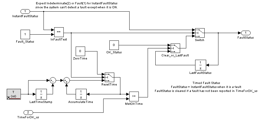
Often a slow rate of [IOFaultStatus.html IO Fault Status] block query is sufficient to allow for reliable fault detection. However, if quicker fault notification is required, then the use of a timed latching mechanism is recommended. Here observing a fault is recognized quickly, but the return to an OK status is slowed by requiring the absence of a fault condition to exist for some amount of time before it is recognized.
Signals
Peak Threshold (mA)
Defines the current threshold to use during the peak phase of operation. The peak phase timer does not start until this threshold is reached when the [#usetimedpeakhold Timed Peak] mode is in use. This is a little different to some other styles of peak/hold drivers supported by MotoHawk™, which are more open loop and start the timer when the driver is initially asserted.
The driver won't enter the hold mode until the peak current has been achieved. Furthermore, failure to attain the peak current may result in an open circuit condition being latched by the driver.
Hold Threshold (mA)
Defines the current threshold to use during the hold phase of operation.
Detect Threshold (mA)
Defines the current threshold that the load current must achieve when actuated for the load to be considered present. An open circuit condition is detected if this current threshold is not achieved. It is also used for short circuit detection per the [#diagnosisprinciples diagnosis principles] discussion earlier.
Block Parameters
| Parameter Field | Values | Comments/Description |
| Name | Alpha-numeric text, single-quote enclosed |
This name will be used by associated blocks like the [ReactionChannelStatus.html Reaction Channel Status] block to reference this channel definition. No special characters, such as spaces, dashes and commas (underscore allowed) |
| Resource | Drop-down list | Module resource for this block (target module dependent). |
| Peak Phase Off Timer Name | Alpha-numeric text, single-quote enclosed |
The name of the [ReactionModuleOffTime.html Reaction Module Off Timer] that supplies the off time attribute to utilize during peak phase operation. This timer can be shared with others and can even be the same as the Hold Phase Timer. |
| Hold Phase Off Timer Name | Alpha-numeric text, single-quote enclosed |
The name of the [ReactionModuleOffTime.html Reaction Module Off Timer] that supplies the off time attribute to utilize during hold phase operation. This timer can be shared with others and can even be the same as the Peak Phase Timer. |
| Use Timed Peak/Hold | Check Box |
Select if a [TimedPeakHold.html Timed Peak/Hold] block shall be used to specify how long the driver should remain in the peak phase before switching to the hold phase. A high impedance load that does not require load current modulation should not check this box. |
| Timed Peak Hold Name | Alpha-numeric text, single-quote enclosed |
The name of the [TimedPeakHold.html Timed Peak/Hold] block that will define the peak time. This timer can be (and often needs to be) shared by multiple reaction channel behaviors. |


