PCM09
Contents
- 1 ECM-5554-112 (PCM-09) Module
- 2 Product Summary
- 3 SEE ALSO
- 4 Hardware Features
- 5 Dimensions
- 6 Simple Block Diagram
- 7 Part Numbers
- 8 Datasheets
- 9 MotoHawk Documentation
- 10 CPU usage on the 112-pin module
- 11 Frequently Asked Questions/Topics
- 11.1 Can I use 24V to power the ECM-5554-112-0904?
- 11.2 Can the PCM-09 be used with the Flexible Encoder?
- 11.3 Why can't I PWM on LSO4,5,6,7?
- 11.4 Is there a minimum PWM frequency?
- 11.5 What do the K, x, and D's in the Target Definition block mean?
- 11.6 Can the ECM-5554-112-0904 connect to MotoTune on all three CAN channels?
- 11.7 I am trying to PWM the injector outputs and am seeing poor resolution. Why?
- 11.8 Can the h-bridges be used as individual high-side drivers?
- 11.9 What are the types or classes of LSO's on the PCM-09?
- 11.10 Do the LSOs support Current Measurement
- 11.11 What are the differences between the PROD and DEV modules?
- 11.12 What are the differences between the 0902 and 0904 modules?
- 11.13 The datasheet says that there are software selectable pull-ups for the speed inputs. How do I set these?
- 11.14 Are the two XDRP power supplies independent from each other?
- 11.15 What is the difference in CAN shielding between the -0902 and -0904?
- 11.16 What is the maximum frequency which can be measured on CNK?
- 11.17 Analog Inputs
- 11.17.1 AN32 and AN33 Reference Voltage
- 11.17.2 How are analog channels referenced to the 5V supply? Which channels are referenced to XDRP1 and XDRP2?
- 11.17.3 Does the ECM-5554-112-0904 have 12-bit ADC's and can they be used for 12-bit resolution?
- 11.17.4 What can be the affect of using analog channels that are actually wired through the VISTA ADC knock chipset?
ECM-5554-112 (PCM-09) Module
Product Summary
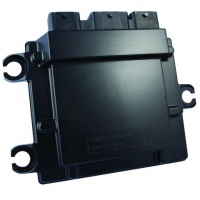
The ECM-5554-112 is a high-end control module capable of operating in harsh automotive, marine, and off-highway applications. Its connector system is environmentally sealed and suitable for engine mounting in many applications. This unit provides 112 connector pins with inputs, outputs, and communications interfaces that support a wide variety of applications. The ECM-5554-112 is part of the ControlCore™ family of embedded controls systems. Woodward’s ControlCore operating system, MotoHawk® code generation product, and MotoHawk’s suite of development tools enable rapid development of complex control systems.
Each Controller is available in ‘F’ (Flash) or ‘C’ (Calibratible) versions. Flash modules are typically used for production purposes. Calibratible modules are typically for prototyping/development only; they can be calibrated in real time using MotoTune.
IMPORTANT! Woodward does not warranty this ECM based on information supplied in this article, but only with an expressed and specific production supply agreement based on customer’s operating mode. Information in this article is subject to change without prior notice. Please contact Woodward sales for more information.
SEE ALSO
Woodward has released to production a nearly similar module in this same form factor. You may also wish to compare PCM09 to PCM112-14.
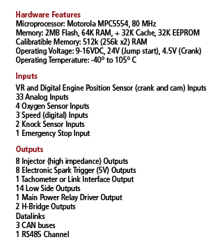
Hardware Features
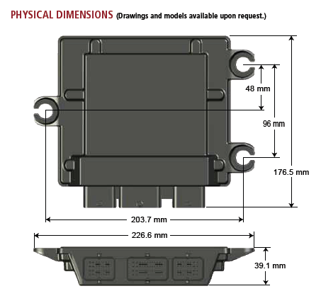
Dimensions
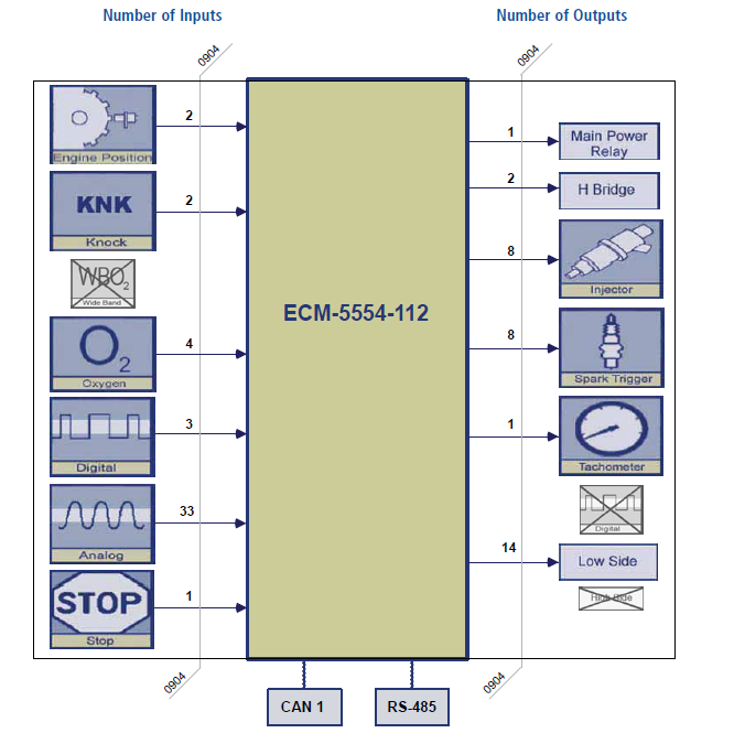
Simple Block Diagram
Part Numbers

Note: Pigtail harness 5404-1215 is now obsolete and is replaced by 5404-1334
Connector kit 8923-1413 is now obsolete and is replaced by 8923-3187
BUY NOW
8923-1628 ECM-5554-112-0904-xD PROD with mounting kit
8923-1629 ECM-5554-112-0904-xD DEV with mounting kit
Datasheets
ECM-5554-112-0904 Datasheet (36350)
GCM-5554-112-1001-C/F Datasheet (36370)
MotoHawk Documentation
ECM-5554-112-0904-xD PROD/DEV
GCM-5554-112-1001 PROD/DEV
CPU usage on the 112-pin module
Unlike the MPC5xx processors, the MPC55xx cannot do double calculations in the hardware. Therefore, all double calculations must be emulated in software. This makes the use of double precision in the model much more CPU intensive.
The use of doubles should only be used where absolutely required. Datatypes should be reviewed and set explicitly in the model to what makes sense for the application.
Setting the Datatype option in the Target Definition block to Single will not force all datatypes in the model to Single.
See CPU usage on the 112-pin module
Frequently Asked Questions/Topics
Can I use 24V to power the ECM-5554-112-0904?
No, the ECM-5554-112 was designed for a system voltage of 12V. There is a transient suppression diode with a wide tolerance that could conduct, creating a power-ground short if used above rated voltages.
Can the PCM-09 be used with the Flexible Encoder?
Yes, Flexible Encoder is supported on both the PCM-O9 and the ECM-OH.
Why can't I PWM on LSO4,5,6,7?
LSO4-7 only available as discrete outputs because of the internal microprocessor/driver chip that drives those outputs. These are not suitable for inductive loads and were designed for O2 heaters.
Is there a minimum PWM frequency?
The minimum PWM frequency on the ECM-5554-112 is 1.19 Hz. Below this, the signal will be clipped to 1.19 Hz. This limit is due to the clock frequency and the size of the counters which hold the period in counts. This is also the lowest frequency that can be read into the module. Below this, the frequency may alternate between 0 and 1.19 hz.
What do the K, x, and D's in the Target Definition block mean?
Information about the different options inthe target definition block:
- K indicates a module with knock development hardware
- x indicates a module without knock development hardware
- P is production hardware revision
- D is development hardware revision
MotoHawk Target Definition Block:
- ECM-5554-112-0902-kD --- PCM0902 module with knock development interface, DV release hardware
- ECM-5554-112-0902-kP --- PCM0902 module with knock development interface, PV release hardware
- ECM-5554-112-0902-xD --- PCM0902 module, DV release hardware
- ECM-5554-112-0902-xP --- PCM0902 module, PV release hardware. Use this target for ECM-5554-112-0902-F00 ("PROD") and ECM-5554-112-0902-CP0 ("DEV") modules.
- ECM-5554-112-0904-xD --- PCM0904 module, DV and PV release hardware. Use this target for ECM-5554-112-0904-F00 ("PROD") and ECM-5554-112-0904-CP0 ("DEV") modules.
Can the ECM-5554-112-0904 connect to MotoTune on all three CAN channels?
Yes, the ECM-5554-112 can communicate with MotoTune on CAN-1, CAN-2, or CAN-3 for display, calibration, or programming.
I am trying to PWM the injector outputs and am seeing poor resolution. Why?
The PCM09 injector FETs are fully protected parts and therefore are very slow to switch. They are designed for frequencies in the <100Hz (6000 rpm). The turn-on delay will be 20-30us and turn-off 65-100us. At 1000Hz, a commanded 50% DC (500us) becomes 420-465us or 42-46.5% DC. They are not designed for PWM (greater than 100Hz) of an inductive load since they do not have internal recirc diodes.
Can the h-bridges be used as individual high-side drivers?
Yes, the half bridges can be PWM'd independently as half bridges, and so can be used as individual high-side drives.
What are the types or classes of LSO's on the PCM-09?
There are 5 ‘classes’ of LSO outputs as follows:
- Injectors - The (8) injector drivers (on PCM0904) use fully protected FETs with a 42V clamp which can handle a non-repetitive (non–PWM) 470mJ of inductive switching energy. They have their own internal flyback protection but it is limited. They could be used to drive a relay. These should not be used for PWM at frequencies higher than 100Hz since the FETs are very slow. Note that PCM0902 used FET’s with much less energy capability.
- LSO4-7 use a high current TrenchFET but it does NOT have its own clamp and is only good for 16mJ (only @25C). These LSO’s are typically used for O2 heaters which are purely resistive.
- LSO2,8-10, MPRD & FUELPR use integrated IC drivers which clamp at 60V and are good for 30mJ @ max temp. These could be used to control a relay.
- LSO3,11 & 12 use integrated IC drivers which clamp at 60V and are good for 45mJ @ max temp
- LSO1 & 13 are current controlled PWM drivers which have internal recirc diodes.
Do the LSOs support Current Measurement
No, current measurement is only supported on the H-bridges of the ECM-5554-112-0904. The LSO outputs feed into the MC33800 pre-FET drivers. The MC33800 has a load resistance feedback feature, but this is not a load current feedback. Here is a link to the MC33800 datasheet https://www.nxp.com/docs/en/data-sheet/MC33800.pdf.
What are the differences between the PROD and DEV modules?
The PROD and DEV are identical other than the extra RAM (external) memory.
What are the differences between the 0902 and 0904 modules?
Here is the full list of changes from PCM0902 to PCM0904.
1) Remove the H1 H-Bridge and replace with two Infineon BTN7930 ½ Bridge devices.
2) Remove the H2 H-Bridge and replace with two Infineon BTN7930 ½ Bridge devices.
3) Remove the On Semi NIF5002 Injector Drivers and replace with the On Semi NCV8403.
4) Remove the TACHLINK transistor (PZT3904) and replace with BFN38 device.
5) Routing of case ground traces to pin B-C3 (replaces CAN2 shield pin).
The datasheet says that there are software selectable pull-ups for the speed inputs. How do I set these?
There is a Set Passive Pull Strength block in the Module Configuration library of MotoHawk (added recently), to allow pull-up configurations. In MotoHawk 2011a CRANK_DG pull strength was first supported. In MotoHawk 2012b, pull strength support for CAM and SPD1 was added.
Are the two XDRP power supplies independent from each other?
Yes, the two transducer power supplies XDRP1 and XDRP2 are independent from each other and the internal core supplies; a fault on transducer power does not cause a fault on the other transducer supply or the internal power supplies.
What is the difference in CAN shielding between the -0902 and -0904?
For ECM-5554-112-0902 (PCM0902): CAN_1 is not shielded, not internally terminated. CAN_2 is shielded, not internally terminated. CAN_3 is shielded, internally terminated 120-ohm.
CANSHIELD2 and CANSHIELD3 are available for shielded bus connections on the respective busses. The internal connection to the PCM ground consists of a 1 ohm resistor in series with a 10 nano-farad capacitor (i.e. no dc path). CAN shielding is not always standardized and this implementation may or may not be appropriate for any specific application.
For ECM-5554-112-0904 (PCM0904):
CAN_1 is not shielded, not internally terminated.
CAN_2 is not shielded, not internally terminated.
CAN_3 is shielded, internally terminated 120-ohm.
CANSHIELD3 is available for shielded bus connections. The internal connection to the PCM ground consists of a 1 ohm resistor in series with a 1 micro-farad capacitor (i.e. no dc path). CAN shielding is not always standardized and this implementation may or may not be appropriate for any specific application.
For the PCM0904 model, pin B-C3 was changed from CAN2 SHIELD to CASEGND. For typical applications, the CASEGND pin should be left not-connected.
What is the maximum frequency which can be measured on CNK?
The datasheet indicates CNK_DG has a filter time constant of 3.2 usec. Therefore the frequency (1/3.2 used) is 310.25 KHz. The CNK_VR input has a filter time constant of 20 usc. 1/20 usec = 50 KHz. The PCM09 module has silicon that should allow most frequencies to be read, but very high frequency readings may become granular depending on the input pin type. Typically inputs up to 12KHz are considered normal and software will read them accurately with good granularity. Above that the user should test and confirm that the granularity and accuracy is sufficient for their application.
Analog Inputs
AN32 and AN33 Reference Voltage
In the original MotoHawk release configuration, prior to 2010b, AN32 and AN33 were set to use a 1.6V reference.
Later versions use a 5V reference. So, AN32 and AN33 may read a higher voltage when model is built with a release of 2010b or higher compared to earlier MotoHawk versions.
How are analog channels referenced to the 5V supply? Which channels are referenced to XDRP1 and XDRP2?
No channel internally references XDRP1 and XDRP2. These supplies are precision tracking supplies that track the internal 5V supply. The MPC5554 ADC effectively uses the internal 5V supply as its ADC reference.
Grounding is effectively a common ground using an internal star point. XDRG1 and XDRG2 just provide sensor ground connections that connect to the internal ground point.
Does the ECM-5554-112-0904 have 12-bit ADC's and can they be used for 12-bit resolution?
See 12-Bit ADC
What can be the affect of using analog channels that are actually wired through the VISTA ADC knock chipset?
The only impact with using these channels is that the ADC reference used by the VISTA is taken from a precision 2.5V reference (VCAL) that is then multiplied by 2, but any pull device will use the internal 5V supply. Ratiometrics could therefore be influenced if the two references are radically different.
The software treats them like any other analog input.
VISTA ADC is effectively 11bit but MotoHawk implicitly handles the conversion from the internal bits to the bit representation desired.
The VISTA ADC include these: XDRP, DRVP, AN12, AN13, AN18, AN19, AN20


