Difference between revisions of "Flexible Encoder"
(→How is a Flexible Encoder System set-up in MotoHawk?) |
(→Variable Cam and the Flexible Encoder) |
||
| Line 729: | Line 729: | ||
= Variable Cam and the Flexible Encoder = | = Variable Cam and the Flexible Encoder = | ||
| + | |||
| + | Phase Reporting can be enabled by checking the Phase Reporting dropdown option on the Absolute or Companion Source Block. Then Variable CAM can be implemented on Flexible Encoder through: | ||
| + | |||
| + | * [http://mcs.woodward.com/content/motohawk/Documentation/CurrentVersion/HTML/motohawk_flexenc_lib_Blocks/FlexibleEncoderSourcePhaseTrigger.html Source Phase Trigger] | ||
| + | * Setting the “Phase Reporting” attribute on the source to a suitable value | ||
| + | * [http://mcs.woodward.com/content/motohawk/Documentation/CurrentVersion/HTML/motohawk_flexenc_lib_Blocks/GetLastFlexibleEncoderSourcePhase.html Get Last Source Phase] | ||
=Flexible Encoder Blockset = | =Flexible Encoder Blockset = | ||
Revision as of 21:12, 14 December 2012
= This Article is Currently Being Created =
Contents
- 1 Why Flexible Encoder?
- 2 Requirements
- 3 Differences Between Flexible Encoder and the Classic MotoHawk Encoder
- 4 How is a Flexible Encoder System set-up in MotoHawk?
- 5 Interpolative Triggers
- 6 Average and Cycle RPM
- 7 Absolute and Companion Sources
- 8 Source Switching
- 9 Diagnostics
- 10 How is a Flexible Encoder System set-up in MotoHawk?
- 11 Pattern Construction
- 12 Variable Cam and the Flexible Encoder
- 13 Flexible Encoder Blockset
- 13.1 Flexible Encoder System Definition
- 13.2 Flexible Encoder Absolute Source Definition
- 13.3 Flexible Encoder Companion Source Definition
- 13.4 Flexible Encoder Pattern Definition
- 13.5 Get Last Flexible Encoder Source Phase Estimate
- 13.6 Flexible Encoder Additional Pattern Path
- 13.7 Flexible Encoder Average Cycle RPM
- 13.8 New Cycle RPM Sample Trigger
- 13.9 Get Last Flexible Encoder Source Error
- 13.10 Get Last Flexible Encoder Source Phase
- 13.10.1 Block ID
- 13.10.2 Library
- 13.10.3 Description
- 13.10.4 Signals
- 13.10.5 Block Parameters
- 14 FAQ: Frequently Asked Questions
Why Flexible Encoder?
It can be expensive to add a new hand coded encoder pattern to MotoHawk both in terms of dollar cost and time cost. The Flexible Encoder allows the user to specify their exact Encoder Specification using an xml file. Also, classic encoder patterns as defined in the Encoder Definition Block are generic. For example, the 60-2 crank; single tooth cam was the same for all users. There was no way to tune the encoder behavior based on system characteristics. With Flexible Encoder, the overall encoder design is shifted to the customer. Therefore, the encoder can be designed for the customer specific application. Teeth location, Keying/Pattern matching, Fault behavior, Impact of Wheel Acceleration, Source Interaction, .. can all be specified specific to the user's application.
The Flexible Encoder offers powerful flexibility over the encoder system design, but also greater responsibility
Flexibility
- Tooth Displacement
- Key Strength
- Number of Keys - can have multiple key points on the wheel
- Source Phasing - you now control how the two, three sources interact in terms of phasing
- Diagnostic Controls
Enhanced capability and new features
- Multiple source solutions
- Active encoder switching - switch between multiple encoders
- Additional diagnostics
- Improved RPM sampling - more flexibility in how that works
- New RPM value - Cycle RPM
- Interpolative TDC and Angle Event Triggers - in classic implementations angle based triggers were on physical teeth. Flexible encoder interpolates.
- Implicit Phase Reporting - variable cam .. can measure the phase between one source and another.
Requirements
MotoHawk Requirements
MotoHawk 2012a or higher is required for Flexible Encoder <br\> <br\> <br\>
Module Requirements
Flexible Encoder is supported on PCM09 (ECM-5554-112-090x) and ECM-OH (ECM-5644A-112-048-120x).
An Enhanced Time Processing Unit (eTPU) is required for Flexible Encoder, so the Flexible Encoder cannot be supported on the 48, 80, or 128 pin module as these do not have eTPU.
Differences Between Flexible Encoder and the Classic MotoHawk Encoder
The Classic Encoder is a one-size fits all Encoder, implemented through an Encoder Definition Block. The Application Designer selects their encoder pattern in a drop down menu. The Flexible Encoder offers requires more application design of the encoder system, but is as the name implies much more flexible and offers additional power over the encoder design as well as additional features. Some of the differences are outlined below.
1. Interpolative Triggers: <br\>
- The Classic Encoder triggers on physical teeth.
- The Flexible Encoder provides for an interplation between teeth.
2. RPM Calculations: Average and Cycle RPM <br\>
- In Classic Encoder, RPM is defined by the Encoder System's TDC and Missing Teeth contributed to average RPM.
- In Flexible Encoder, the Application Designer controls separately where average RPM is calculated. RPM Sample Points is a vector setting in the Source Definition Block.
- Average Cycle RPM is a also new calculation feature of the Flexible Encoder.
3. How Teeth Are Handled: The flexible and classic encoder systems differ in terms of how they handle missing and extra teeth.
- In Flexible Encoder, All Physical Teeth Matter, and ONLY Physical Teeth Matter. In Classic Encoder, Missing Teeth Contribute to the System.
- All Teeth Matter
- In a 4+1 pattern the extra tooth matters for the flexible encoder. So, the tooth's position needs to be defined precisely. It contributes to instantaneous RPM, and provides a High-Res trigger event.
- In classic encoder the extra tooth doesn't matter - it is only used to synchronize.
- No Concept of Psuedo Teeth.
- In flexible encoder, you won't get High-Res trigger events from the missing teeth.
- The classic encoder would provide a High-Res trigger event on missing teeth.
- All Teeth Matter
4. Additional Diagnostics:<br\>
- Flexible Encoder allows for additional fault reporting, Synchronization Fault, HalfCycle Fault, Loss Fault, Inversion Fault, Phase Fault, Absent Key Fault, Reverse Rotation, Bad Halfcycle Window.
5. Source Switching:<br\>
- Flexible Encoder allows the system to switch from one Absolute Source to another, should the application determine that it is required.
6. Greater design control of Encoder Pattern:<br\>
- Flexible Encoder allows the application designer greater control over the Encoder Pattern. Such things as number of keys (ex. missing teeth, wide teeth), key strength, teeth to ignore, key tolerance (to allow a key to be detected while allowing for variation due to acceleration), etc can all be designed to meet individual system requirements.
<br\> <br\>
How is a Flexible Encoder System set-up in MotoHawk?
There are many considerations in designing a Flexible Encoder System. We will try to condense the setup here to a few number of steps. Then see the Flexible Encoder Block Help help for additional details.
1. Develop Your Encoder Source Pattern(s) on an xml file and then use the MotoHawk Flexible Encoder Pattern Definition Block to bring the pattern(s) into your model. The Flexible Encoder Additional Pattern Path block can be used to specify the path to the xml files, for the model.
2. Use the MotoHawk Flexible Encoder Absolute Source Block to define the Absolute Sources in your System. An Absolute source is a source that can be used to provide absolute crank angle position. You would have one Absolute Source Definition block for each Absolute source in your system.
3. Define any companion sources (not used to provide absolute crank angle position, ex. camshaft pattern) in the system using the Companion Source Definition Block. 4. Use the MotoHawk Encoder System Definition Block to group a number of Absolute Sources into a System.
5. Use the Flexible Encoder Average Cycle RPM, Cycle RPM Trigger, MotoHawk Average RPM, or MotoHawk Instantaneous RPM blocks to give these calculated values to the control model.
6. Flexible Encoder Get Last Flexible Encoder Source Error can be used to give error information to the control model.
7. If you need to design a variable cam system, there is a Phase Reporting dropdown option on the Absolute or Companion Source selection. Then, the Variable CAM is implemented on Flex Encoder, through the use of the Flexible Encoder Source Phase Trigger and Get Last Source Phase blocks.
<br\> <br\>
Interpolative Triggers
In classic encoder, the TDC would be reported on the next physical tooth. Resolution is one tooth. Flexible Encoder provides for an interpolation between teeth.
See diagram below:

In legacy encoder you need to schedule based on where you see the physical teeth. This can particularly be a problem if there is a low number of teeth. But, with flexible encoder the trigger is interpolative.
On flexible encoder, interpolation resolution is .0625 deg crank angle.
See diagram below:
In legacy encoder you need to schedule based on where you see the physical teeth. This can particularly be a problem if there is a low number of teeth. But, with flexible encoder the trigger is interpolative.
On flexible encoder, interpolation resolution is .0625 deg crank angle.
Average and Cycle RPM
Average RPM
- In Classic Encoder, RPM is defined by the Encoder System's TDC and Missing Teeth contributed to average RPM.
- In Flexible Encoder, the Application Designer controls separately where average RPM is calculated. RPM Sample Points is a vector setting in the Source Definition Block.

Average Cycle RPM
Average Cycle RPM is a new calculation offered with the Flexible Encoder. It can be acceseed with the MotoHawk Flexible Encoder Average Cycle RPM block, and can be used in conjunction with the Flexible Encoder Cycle RPM Trigger Block to read an updated RPM.
In image below, the average RPM is set up to be TDC based.
- Each time encoder sees the next period defined for Average RPM (dark blue, aqua blue, .. green), a new period sum is calculated. When the blue one comes in, fill in the blue. When blue comes in again, blue gets filled in again.
- The Period Sums are added to give Average Cycle RPM.
- A Cycle RPM Trigger executes on each data element
If Cycle RPM is Invalid the Average RPM is Reported (zero speed, some encoder errors such as sync)
It is a FIFO based RPM

How do encoder faults impact Cycle RPM?
It depends on the fault. For a syncronization fault, the Cycle RPM is invalid and the Average RPM will be reported. Other faults, such as Absent Key Fault that do not invalidate position determination would not cause the Cycle RPM to be invalid.
Does Pseudo Encoder support RPM Triggers? No
<br\> <br\><br\>
Absolute and Companion Sources
Absolute Source: An encoder source that may be used by the encoder system to provide crank angle position of the wheel.
Companion Source: An encoder source that it is not used to provide absolute crank angle position. Companion sources are used to help synchronize an absolute source (e.g. tooth synchronizer pattern) and/or provide halfcycle information (e.g. camshaft pattern).
Absolute Source
An Absolute Source is defined in the Flexible Encoder Absolute Source block. An Absolute Source refers to an encoder source that may be used by the encoder system to provide crank synchronous behaviors (like injection) with a high resolution tooth interpolated absolute crank angle position. The actual resolution of the interpolation is dependent upon the number of teeth of the wheel, but in general it will be 0.0625 degrees crank angle.

There are many parameters to set in the Absolute Source Definition Block, so see the Block Help for complete list. Here are a few that may be initially confusing -
Loss Companion
This is the name of the Encoder Source that this source uses to detect loss. This can be another Absolute or Companion Source. Loss is flagged if this source detects a certain number of teeth (set in Teeth Before Loss) on another source.
Synchronization Companions
What is a Synchronization Companion?
Some sources (semi-unique) such as a 36 tooth wheel with 36 equally spaced teeth require a second source to determine absolute crank angle position. A Unique Pattern (ex. 60-2) does not require a Sync Companion, because the position of the wheel can be absolutely determined when the unique key is seen.
A synchronization companion is a companion source that issues a synchronization event to another source when it observes its key. The receiving source uses this key to transform the next [FlexibleEncoderPatternDefinition.html#type_standardsemiunique semi-unique] key that it observes into a unique key. Absolute position can be inferred once the key has been transformed into a unique key.
Some sources may be a Sync Companion, and also give half cycle information - for example a crank wheel with 36 equally spaced teeth and a single tooth cam wheel. In this case, the single tooth cam wheel is specifying which of the 36 crank teeth is being seen, and also what half cycle the system is in. In such a case, the Half Cycle Companion should not be configured for use, as it inherently provides the half cycle information.
For Example: Consider the 3x12M2 pattern in the figure below. Three instances of a missing tooth key are annotated. Each of these instances are the same, which is why the key is said to be semi-unique, and why absolute position of the wheel can't be inferred without a companion. The single key of the 4+1 synchronization companion signals the 3x12M2 source when the key is observed, then the next observed semi-unique key to be marked as unique. A pattern that is to be used for synchronization should have only one standardunique unique key defined so that the system can easily identify what key provides the synchronization event.

Synchronization Window Configuration
The Synchronizaton Window allows ratification of the synchronizing event. The maximum synchronization window annotation describes the worst case window where a synchronization event could occur for this 3x12M2 pattern. The window is measured back from the missing tooth key and has units of teeth. For the 3x12M2 wheel the maximum synchronization window value is 10. No more than 9 teeth should ever be observed between observing the synchronization event and observing the semi-unique key. However, this particular setup happens to have the key event on the synchronizing source (4+1) occurring within the missing tooth region and so the window could be reduced to 0 for this example. Events that fall outside the specified window are ignored.
TDC Synchronization
The absolute source encoder pattern for some encoder systems has semi-unique keys that represent engine TDCs. A 4 tooth encoder (4X) used in a 4-stroke application has one tooth per TDC when in use with an 8 cylinder application. Each tooth is a semi-unique key on such an encoder. Without a synchronization companion the absolute source could guess what key represents TDC#1 since each key is known to be a TDC. The system may just assume that the next observed key represents TDC#1 and force synchronization. The ignition and fuelling system must be capable of allowing the synchronization to be guessed like this and the absolute source must have the same number of keys as there are TDCs else the guess could be wildly incorrect. That is it the engine system must support distributed ignition (or not control ignition), banked fueling (or not control fueling) and have the same number of TDCs as there are semi-unique keys before this approach could be used. The TDCSync tick box enables this option. If the synchronization companion were to be diagnosed as having failed (typically a loss fault), then synchronization would be forced to occur on the first key observed after the failure had been flagged when this attribute is TRUE.
Half Cycle Companion
A Half Cycle Companion is a Companion Source that tells the Encoder System which half cycle the system is in. An example would be a 60-2 crank wheel with Half Cycle Companion being a 4+1 wheel on the cam.
Halfcycle Window Configuration
All sources that utilize a halfcycle companion will need to configure the halfcycle [#halfcyclewindowteeth window]. Incorrect configuration can lead to rogue halfcycle faults.
Halfcycle Window Configuration for HalfCycleEncoding=window

The example above has an arbitrary crank key defined that identifies tooth #1 on the crank wheel. The cam tooth is an edge key (every observed tooth of an edge key is considered to be a key) and as such needs to be looked for in a window. The pattern's HalfcycleEncoding would have been configured for window. The halfcycle window occurs between crank tooth #13 and crank tooth#1. If at least 5 crank teeth have been observed prior to observing the crank key then the encoder source can infer that the cam tooth would have occurred if it was going to occur. Note that the crankshaft revolves twice for one camshaft revolution and so every second key will occur without the cam tooth occurring. The encoder source thus infers the halfcycle by looking for the presence or absence of the cam tooth within this window. Configure the window to be too small and the encoder will look in the wrong region and incorrectly assume the halfcycle state that is applicable when the cam tooth is not observed. Configure the window too large and the encoder startup performance is compromised because all the window teeth need to be observed before halfcycle determination can occur.
An encoder that needs to use a companion that is employing HalfcycleEncoding=window should only have a single unique key defined. To define more will confuse the implementation because it does not associate the window to a specific key.
Halfcycle Window Configuration for HalfCycleEncoding=state
The halfcycle [#halfcyclewindowteeth window] is still important for start-up performance. Here the window defines how many source teeth on the crank (normally) need to be observed before the source can assume that the halfcycle companion will have synchronized. The window is always measured relative to the worst case key location. The figure [FlexibleEncoderPatternDefinition.html#FlexiEnc_XML_HalfCycleEncoding here] illustrates.
Companion Sources
Companion Source is also an encoder source except that it is not used to provide absolute crank angle position. Companion sources are used to help synchronize an absolute source (e.g. tooth synchronizer pattern) and/or provide halfcycle information (e.g. camshaft pattern). There is often fewer resources required by a companion only source compared to the resources needed by an Absolute Source and so more module resources can usually support such inputs.
A Companion Source is Defined by the MotoHawk Flexible Encoder Companion Source Definition Block.

Loss Companion
A Companion Source will always have a loss companion, because a companion source will never exist in design without at least one absolute source. Loss is flagged if this source detects a certain number of teeth on the referenced source.
Key Event Aligns With Companion Source
The Key Event Aligns with Companion Source tick box is used to signal that a key event occurs in the vicinity of a companion key event. This is most commonly used by a tooth cam or synchronizing source that has an edge that occurs in the vicinity of a crank tooth. When the key event occurs near a tooth there is a risk that system variations will see the key event from the source associated with different teeth on the crank. This will lead to unexpected operation.
Consider a 36 tooth crank shaft encoder that uses a single tooth companion to provide synchronization. If the synchronization tooth occurs in the vicinity of a crank tooth then there is a chance that the synchronizer tooth may occur before or after that crank tooth. This would mean that the key event will be associated with different crank teeth, yet the intention would be to want to always associate this tooth with the same crank tooth. In this situation the [#keyeventalignswithcompanionsource Key Event Aligns with Source] would be set to true. If it occurred more toward the middle of the crank teeth then it would be set to false.

Whilst a tooth companion was used as an example, this attribute could also be used for a 6+1 companion that was providing a synchronizing event to a crank encoder that had 36 equidistant teeth.
Phase Error Examples

Source Switching
In Flexible Encoder the Application can switch from one source to another and that switching is handled automatically.
The classic encoder does not allow for source switching
For example, if the application detects that the crank signal is broken, the application can switch to the cam encoder or another source. Both sources are defined as absolute sources, and the system is set up to define 'loss companion'.
Switching the Active Source is a Decision of the Application Designer
The overall System is Defined in the Flexible Encoder System Definition Block, shown below.
All system sources are listed in this block and
Pseudo Encoder is just a different source

Source
This unsigned integer signal input port defines what source the model wants to be the active source. The value will correspond to the Crank Position Source instance or be zero if the pseudo encoder is to be requested.
In the System Definition block above, if you put a '1' in the Source input port, you would use Source 1: CnkEncoder. You could define source 2, source 3 etc. If you put a '5' into Source input port and there wasn't a Source 5, you would get an error from the Active Source output of the block.
The Enable input to the Pseudo Encoder shown below is ignored, pseudo encoder must be defined as any other source in the system.

Active Source
This signed integer outport signal defines what source is currently considered to be the active source. The value will correspond to the Crank Position Source instance that is considered to be the active source, or to zero when the pseudo encoder is in use, or a negative number of no source is active. An encoder system without an active source can't detect crank angle position and thus prevents the support of crank synchronous behaviors.
When to Switch
The encoder system will likely want to switch encoder sources when it supports redundancy and the active source is issuing faults. While the application model ultimately controls what Absolute Source the encoder system will use for its crank synchronous behaviors, when to switch should be considered based upon the desired performance.
For example, observing a Loss Fault will nearly always result in switching to an alternate source. A Synchronization Fault may also constitute a need to switch because the signal should never result in synchronization faults if it is operating correctly. However a Halfcycle Fault or an Inversion Fault may not force a switch. A Halfcycle Fault can result because of setup problems and/or because of problems with the companion sensor. The inversion fault implies a setup problem.
Consequences of Switching
The encoder system aims to make a switch between encoder sources as seemless as possible, but it is not instantaneous.
A switch will result in all crank synchronous pulses (like injection and ignition) terminating before the switch is made. The effective encoder relative timings will need to change when the source is switched and consequently the existing timings can't be trusted. Therefore the pulses must be turned off. Furthermore the internal tracking system must achieve a lock with the new encoder source. A lock can only be achieved after two teeth have been observed by the new active encoder source. Consequently there will be a delay between applying the switch and that new source allowing crank synchronous pulse generation to occur.

<br\> <br\> <br\>
Time Delay Before Attempting Sync

Some Source Switching Considerations
Does the application allow failover switching while running?
Does it allow failover switch only as a pre-curser to cranking?
How does the application handle an 'absent key' fault?
How are sensor faults on the active source used to drive source switching?
Loss Fault on the active absolute source would cause a switch.
Repeated 'synchronization' type faults could cause a switch
- Application must decide... how many faults? what type of faults?
There should be no faults on the source that is switched to. <br\> <br\>
Diagnostics
Fault Data for the Flexible Encoder is reported to the Application using the Get Last Flexible Encoder Source Error block.

The user references the block to either an Absolute or a Companion Source, and the fault value for that source is given on the Error Outport.
Available Faults
Synchronization Fault (value=1)
A source suffers a synchronization fault when the tracked position does not match the calculated position. Tracked position is updated each time a source tooth is observed. Calculated position is updated each time a [FlexibleEncoderPatternDefinition.html#type_standardunique standard unique] key is observed. It is checked once updated and this fault is issued when the two don't match and the source has previously achieved synchronization. The tracked position is not valid until the first calculated position has been observed and so synchronization faults are not possible until this first key match has occurred. This is important to note because the system may never achieve an initial synchronization if the key setup is wrong.
Halfcycle Fault (value=7)
A halfcycle fault is observed when the tracked position does not match the calculated position, but a [#syncfault Synchronization Fault] has not been observed. It implies that the system has a problem with the halfcycle determination, which could be due to companion sensor setup.
Loss Fault (value=2)
A loss fault occurs when sufficient teeth have been observed on a companion sensor without having observed any teeth on the sensor under test. See [FlexibleEncoderCompanionSource.html#teethbeforeloss Teeth Before Loss] configuration. A loss fault can only be detected when a companion sensor exists because the system requires an alternate source of rotation detection to detect sensor loss.
Inversion Fault (value=3)
An inversion fault requires a specialized [FlexibleEncoderPatternDefinition.html#type_signalinverted inverted] key to be specified. It is used to attempt to detect an inverted signal connection.

Phase Fault (value=4)
Issued when one source is not within the specified phase of another. A source is said to have suffered a phase error if its zero tooth (as defined by the [FlexibleEncoderPatternDefinition.html#XML_PhysicalTeeth Pattern Definition Physical Teeth] entry of this source's referenced pattern) falls outside the window defined by [FlexibleEncoderCompanionSource.html#startphasewindow Start Phase Window] and [FlexibleEncoderCompanionSource.html#endphasewindow End Phase Window]. See [FlexibleEncoderCompanionSource.html#FlexiEnc_PhaseError example figures] that illustrate this error.
Absent Key (value=5)
An absent key fault or missed key fault results when an expected key is not observed. An absent key is detected by noting how many encoder source teeth have been observed since the last standard key was observed. Configured by the [FlexibleEncoderPatternDefinition.html#XML_TeethBeforeAbsentKeyFault pattern] in use by the named source.
Reverse Rotation (value=6)
Reserved for future support.
Bad Halfcycle Window (value=8)
This errror is only observed when halfcycle [FlexibleEncoderPatternDefinition.html#XML_HalfCycleEncoding window] encoding is in use. Consecutive occurrences of this error suggests that the halfcycle window has not been correctly configured. It occurs when halfcycle events are being observed, yet none of these events are being observed within the window. Consider a tooth cam in a crank/cam system. This error would be flagged if, say, the tooth cam event was occurring 10 teeth before the crank's key, yet the window was only set to 8.
How is a Flexible Encoder System set-up in MotoHawk?
There are many considerations in designing a Flexible Encoder System. We will try to condense the setup here to a few number of steps. Then see the Flexible Encoder Block Help help for additional details.
1. Develop Your Encoder Source Pattern(s) on an xml file and then use the MotoHawk Flexible Encoder Pattern Definition Block to bring the pattern(s) into your model. The Flexible Encoder Additional Pattern Path block can be used to specify the path to the xml files, for the model.
2. Use the MotoHawk Flexible Encoder Absolute Source Block to define the Absolute Sources in your System. An Absolute source is a source that can be used to provide absolute crank angle position. You would have one Absolute Source Definition block for each Absolute source in your system.
3. Define any companion sources (not used to provide absolute crank angle position, ex. camshaft pattern) in the system using the Companion Source Definition Block. 4. Use the MotoHawk Encoder System Definition Block to group a number of Absolute Sources into a System.
5. Use the Flexible Encoder Average Cycle RPM, Cycle RPM Trigger, MotoHawk Average RPM, or MotoHawk Instantaneous RPM blocks to give these calculated values to the control model.
6. Flexible Encoder Get Last Flexible Encoder Source Error can be used to give error information to the control model.
7. If you need to design a variable cam system, there is a Phase Reporting dropdown option on the Absolute or Companion Source selection. Then, the Variable CAM is implemented on Flex Encoder, through the use of the Flexible Encoder Source Phase Trigger and Get Last Source Phase blocks.
Pattern Construction
The Flexible Encoder allows an XML encoder pattern definition to be included in a model. This gives the application the flexibility to tailor the definition to take into account various nuances of the pattern's operation, including the strength of the pattern matching used to synchronize that pattern. This block is used to reference an XML definition within the model. Use the Encoder Pattern Path Block to specify the location of custom pattern definitions.

Overview
A Flexible Encoder XML encoder pattern definition must contains the following nodes within an < Encoder > node (unless the node is marked as optional):
- Name - Optional
- DescriptiveName
- PhysicalTeeth
- Keys
- TeethBeforeAbsentKeyFault
- DefaultKeyTolerance
- ClrHalfCycleTooth
- SetHalfCycleTooth
- HalfCycleEncoding
- EquidistantToothDisplacement_deg
Name
Name is typically matched to the file name and is optional.
Descriptive Name
The first step is to give the pattern a descriptive name. The DescriptiveName identifies this encoder pattern definition to MotoHawk. This name should be unique for all the encoder patterns supported by a model. You can name the pattern whatever you want, but the way MotoHawk associates the pattern is the Descriptive Name. In the below example, this is custom18M1.
- Hint: Put 'custom' in front of the pattern, so you won't have a name clash with any patterns predefined in MotoHawk.
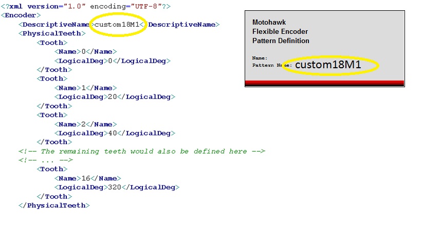
- Hint: Put 'custom' in front of the pattern, so you won't have a name clash with any patterns predefined in MotoHawk.

Physical Teeth
Define the Physical Teeth for your pattern. PhysicalTeeth houses the definition of the encoder pattern's tooth arrangement. Each tooth should have a Name and a LogicalDeg node. Optional attributes include StartDeg and EndDeg.
- Start at 0. You must define tooth 0, and you must start at tooth zero.
- Define each tooth, relative to tooth zero.
- Don't Include Missing Teeth.
- Start where most equidistant teeth are for best compression
Name
Name is the tooth name and by convention is a number that starts at zero and increments with each definition.
LogicalDeg
LogicalDeg defines the angle about the wheel relative to tooth zero (which is zero degrees) that the synchronous edge of the pulse train that would result when that tooth was observed. The synchronous edge is set by the Sync Polarity a source block and should correspond. Convention dictates that tooth zero should be selected to be the start of a series of similar tooth definitions. In the following example, where an 18 minus 1 pattern is defined, tooth zero is identified as the first tooth after the missing tooth. This ensures that all of the teeth have the same spacing from one another, which helps optimize internal performance.
<br\> <br\>
What follows is a partial definition of the 18 minus 1 crank encoder source depicted in the diagram. Note that the diagram has been drawn in the cam angle domain so that it can be used to explain the relationship between a cam encoder source and a crank encoder source (which rotates twice for a single rotation of the cam). The 18 minus 1 crank encoder pattern does not have two missing teeth. It has just be drawn twice to account for the two rotations that the crank source will undergo for a single revolution of the cam source.

StartDeg and EndDeg
StartDeg are EndDeg optional nodes that have no bearing on the definition. These could be used to encode information that would allow the wheel to be drawn by a graphical tool. Only LogicalDeg is important as it is this angle that the encoder definition will associate the tooth to.
Equidistant Tooth Displacement Degrees
This attribute identifies what the approximate equidistant tooth displacement of the encoder pattern being defined. The 18 minus 1 encoder wheel has an EquidistantToothDisplacement_deg of 20 degrees. This attribute is used to assist pulse scheduling engine when this encoder pattern is in use. Some encoder patterns, like a tooth cam, are not used for pulse scheduling. A pattern like a tooth cam is a companion pattern that may only be used to provide half cycle information. However it still constitutes a pattern and as such this node should still exist, it would just have a value of of 360. It can be approximate. Round up. For 60-tooth wheel, the value is shown below as 6.

Key Construction
<br\> Keys Describe how to synchronize a pattern and are identified by the application developer. <br\> <br\>
A key is a pattern that is used by the flexible encoder system to facilitate pattern synchronization. Pattern synchronization needs to occur before the encoder system can associate each observed tooth to a specific angle on the encoder wheel. The flexible encoder observes the input signal(s) and searches that signal for a key(s). There can sometimes be more than one.
Keys are Constructed from RATIOS.
- A ratio is used in the construction of a KeyValue
- A sequence of Ratios forms a detectable pattern
A Key is constructed from a sequence of Ratio values. A ratio of tooth displacements is invariant for constant speed of rotation, regardless of the speed of rotation, and thus allow variations in tooth to tooth displacement to be identified.
Consider a tooth that is removed from a wheel of equidistant teeth (commonly referred to as a missing tooth pattern) as shown on the 8 minus 1 wheel below. The missing tooth provides a synchronization marker because it uniquely identifies a point on the wheel. Tooth Period is shown as Tw, Tx, Ty, and Tz below.
The following patterns can be seen:

The ratio of angle displacements just before and after the missing tooth will be 1.0, 2.0 and 0.5.
- Neighboring teeth are separated by the same displacement and so will have a ratio of 1.0.
- The ratio between the missing tooth region and the previous equidistant tooth will be 2.0,
- The first tooth after the missing will have a ratio of 0.5 (because the displacement of this tooth when compared to the previous tooth is half).
The encoder system can calculate displacement ratio by measuring the time taken to traverse the teeth. The time taken to traverse a displacement is proprotional to displacement for constant speed of rotation so tooth displacement ratios can be inferred by taking the ratio of neigbouring tooth periods (the time observed between teeth). Thus the encoder system could search for a ratio of 2.0 and know that the tooth after the missing tooth had just occurred. Alternatively it could search for 1.0 followed by 2.0 as this is also unique. It could search as well for a 1, followed by a 2, followed by a 0.5.
DefaultKeyTolerance allows constant speed of rotation to be assumed by installing a window of acceptable ratio values, to provide tolerance for acceleration.
Combining ratios can increase the strength of the key.
NNote that whilst the key "2.0" or the key "1.0, 2.0" are both unique, a system could not define both of these keys because a unique key shall not contain the entirety of another key. It would also serve no purpose to detect both keys.
A pattern may support more than one Key and there are also different types of keys.
Key
A key is constructed from a sequence of KeyValue that are housed within a KeyValues node. Each KeyValue has a Tooth and a Ratio node.
The most common key type are those that are used by the encoder system to calculate the position on the wheel. In other words, the encoder is able to determine the position of the last observed tooth about the wheel when an entire key match has occurred.
ToothPosition is used to define the tooth position a particular key will detect. The diagram below illustrates a 3 tooth key. ':Note that ToothPosition has the value of 1, which corresponds to the last Tooth in the key. So this key detects tooth position 1. The encoder system knows that it has just observed tooth #1 whenever it observes this key on this encoder source.
- It knows this because the type is standard unique. Standard keys provide positional information. A standard key that is unique means that this key definition only exists once within the pattern. The construction of this key and the use of ratio is further detailed under the section titled 'ratio'. ToothPosition is optional/meaningless if the type is not a standard key.

Types of Keys
| type= | Definition |
|---|---|
| standard unique | Standard keys provide positional information. A standard unique key shall only exist once within the pattern and thus will convey absolute position if that key is ever observed. |
| standard semi unique |
A standard semi unique key provides positional information, but is not unique. The 3x20M2 pattern contains a semi-unique key. A semi-unique key requires a synchronizing source to exist that will provide an event that can uniquely identify one of the semi-unique keys. See [FlexibleEncoderAbsoluteSource.html#synccompaniondetail here] for an example. A standard semi unique key implies that there are multiple keys that are the same (there are 3 instances of the semi-unque key in the 3x20M2 example). However only one instance of the key would be defined and it's ToothPosition would be configured for the semi-unique key instance that will be marked as unique by a companion synchronizing source. |
| signal inverted |
A signal inverted key does not provides positional information. Instead it is looking for a pattern that may occur if the sensor of the encoder source is not connected correctly. It would be used as a diagnostic. See [GetLastFlexibleEncoderSourceError.html#FlexiEnc_SignalInversion here] |
| companion support |
A companion support key does not provides positional information. Instead it is used to convey an occurrence event that another source is looking for. A single tooth synchronizer pattern would utilize a companion support key to signal a source with semi unique keys when it occurred so that one of those semi-unique keys could be marked as unique (because it is the first to occur after the companion support key). |
Standard Unique Keys
Standard: Provide Sync <br\> Unique - Stands Alone <br\>
The 18M1, 60M2, 36P1 would all be examples of Standard Unique Keys.
Standard Unique is something you would use for something like 18M1, 60M2,4P1.

Standard Semi-Unique Keys
Standard: Provide Sync Semi-Unique - more than one
Example: There are three sets of missing teeth pairs. There is a key at missing tooth regions, but if encoder detects the key it doesn't know where it is.
SEMI-Unique: The same key but more than one.

 <br\>
You could also throw the other keys out when you are defining the pattern based on physical teeth, and then only use one key.
<br\>
You could also throw the other keys out when you are defining the pattern based on physical teeth, and then only use one key.
Edge Key A Key that has no values is referred to as an edge key. Every observed tooth of an edge key is considered to be a key. A tooth cam like the example CamTooth below or a 36 equidistant tooth wheel would utilize such keys.
Companion Support
A tooth cam like the example CamTooth below is an example of an edge key, that is being used as as a companion support key.

If the pattern was 36 equidistant teeth, it would be providing positional information so would be standard-semi unique, rather than companion support as shown in xml file above.
Tooth
This is a convenient marker to associate a key value entry to a PhysicalTeeth Name entry. The circled values in the diagram below illustrates the relationship between a physical tooth and the key value.
This is the Sync Point:

Ratio
Ratio defines the expected matching relationship at this tooth. The relationship always relates to measurements that occur prior to observing the synchronous edge of the signal (which corresponds to a LogicalDeg entry).
Pulsewidth or ToothPeriod? Either the period between the tooth edges or the width of the teeth can be used for pattern detection. Thus Keys may have a type that is either toothperiod or pulsewidth.
- Use toothperiod when the Ratio is constructed from adjacent tooth periods.
- Use pulsewidth when the Ratio between the tooth period and the tooth's width is to be used to construct the key.

ToothPeriod: When toothperiod matching is in use the ratio is defined as the angular advancement of the tooth previous to the tooth under examination divided by the angular advancement from the previous tooth to the tooth under examination.
The diagram above highlights this with colors.
Consider If the Ratio determination for Tooth#0. Tooth#0 is under examination and is the first tooth after the missing tooth. It is 40 degrees advanced from the the previous tooth (because there was a missing tooth and each tooth is nominally displaced 20 degrees apart). The tooth previous to the tooth under examination (Tooth#0) is Tooth#16 and it is 20 degrees advanced from the tooth previous to it (Tooth#15). Therefore the Ratio is 2.0.
The 18M1 Wheel shown below is based on Period of each tooth in the sequence. So, equidistant teeth gives 1, gap gives 2, then next tooth/gap gives 0.5 for Tooth Period.
PulseWidth: The width of a tooth can also be used for pattern detection, for example on some digital type patterns that don't have extra teeth or missing teeth, they change the width of a tooth or some teeth. . If pulsewidth were being used then the ratio is defined as the width of the tooth divided by the degrees of advance from the previous tooth. Such ratios should always be smaller than 1.0. The diagram below illustrates a pulsewidth based key. Note that there can be more than one key.

Key Ratio resolves to .0625 degrees, it is a 4 bit fixed point value. So if you set ratio to 2.7, it would be rounded. Also, Ratio cannot be larger than 15.
Teeth Before Absent Key Fault
Standard keys convey position and are thus expected to always be observed. An absent key fault or missed key fault results when an expected key is not observed. An absent key is detected by noting how many encoder source teeth have been observed since the last standard key was observed. The TeethBeforeAbsentKeyFault attribute allows the developer to define this value for their pattern.
An appropriate value for this attribute would be 19 if the 18M1 example pattern was in use. The encoder system expects to observe the missing tooth key once per revolution and there are 17 physical teeth per revolution. However rotation may initially start within the key, which is 3 teeth wide for this particular version of the 18M1 pattern. The key won't match unless the entire key is observed and thus starting within the key will not result in a match. Therefore it's possible to legally observe 17+2 teeth and still not have observed the key.
For the 4 toothed pulsewidth the value would be 3. There is more than one key so a key should always have been observed before a full rotation has occurred.
Default Key Tolerance
Defines the Plus or Minus window that is applied to each ratio value to create an acceptable key range. The value saturates to zero or to a maximum. The wheel will be accelerating, even at a constant speed the pistons are firing, so there will be some localized accelerations if you look at Instantaneous RPM. This gives a tolerance on the Key Ratio to account for accelerations.
Choose a value that will still allow normal teeth to be rejected as keys, while allowing for acceleration.
The following missing tooth example illustrates how the tolerance works and why it is needed. The simple missing tooth key looks for a ratio of 2.0. Under acceleration this ratio won't be observed yet the missing tooth has clearly occurred. To reliably detect this key requires a tolerance value of 0.4 to be used. This creates an acceptance window of 1.6 to 2.4, which 1.64 falls within. If the tolerance had been 0.3 then the observed ratio of 1.64 would not have qualified as a legal key match because it falls outside the 2.3 to 1.7 window.

Remember, resolution is 0.0625.<br\>
When you are developing a pattern on the bench, test at all ranges of your RPM with Margin. <br\> <br\> <br\>
Half Cycle Source Attibutes
Some encoder sources can be used to provide halfcycle information. Such sources are located on a camshaft and are used to identify which halfcycle a particular engine revolution is associated to (the crank shaft rotates twice as fast as the camshaft). Pattern Half Cycle State attribute exists on all patterns that you define, but may not be applicable to all patterns but you still have to define the values.
All pattern definitions shall must have the following attributes:
- HalfCycleEncoding
- ClrHalfCycleTooth
- SetHalfCycleTooth
HalfCycleEncoding
This attribute specifies how half cycle is encoded. There are three possible schemas, key state, pin state and windowed.
| HalfCycleEncoding | Description |
|---|---|
| state |
Used when the pattern supports standard unique keys. Such patterns are able to synchronize themselves without assistance from a companion source. Therefore, once synchronized, the source can be queried for its current position and that position used to indicate whether the system is currently in the first or second half of the cycle. This decision is made using the ClrHalfCycleTooth and set SetHalfCycleTooth attributes. |
| pin |
Used when the state of the sensor pin implies the halfcycle state. So a halfmoon sensor could use this style of encoding. To be valid the pin state must reflect the correct halfcycle for each standard unique key that is defined on the absolute source. For example, an 18M1 crank shaft encoder could utilize pin HalfCycleEncoding if the pin would be high around the missing tooth (where the key would likely be defined) for one rotation. pin HalfCycleEncoding is assumed to always be available to the encoder system, which implies that the pin state of the companion will always represent the halfcycle state when a standard unique key is observed on the absolute source that requires the halfcycle information. |
| window |
Window encoding is used when the pattern does not support any of its own standard unique keys and the pin state of the pattern does not align with the keys of the absolute source that requires the halfcycle information. The 18M1 with tooth cam figure would utilize the window approach because a tooth cam can't support state or pin encoding. The window defines the region of teeth relative to the standard unique key of the crankshaft source. The 18M1 waveform highlights the halfcycle window. Note that the tooth cam pulse only occurs relative to every second missing tooth (because it rotates at half the speed). Importantly, window halfcycle encoding has been implemented such that it can only be utilized on companion source that has a single standard unique key. If the source in use has more keys than this then all but one of the keys should be deleted so that it will work with the window approach. |
ClrHalfCycleTooth
The half cycle is represented as a Boolean value - either cycle 0 or cycle 1. The Encoder does not care which half cycle is which, only that they are defined. Calibration of TDC offset gives half cycle position for the system.
The ClrHalfCycleTooth clears the halfcycle Boolean when this cycle is observed.
Half Cycle 0 <br\> <br\>
SetHalfCycleTooth
This attribute sets the halfcycle Boolean when this tooth is observed.
Half Cycle 1
Example:
In the example below, inside ring when tooth zero is detected then Half Cycle State is Blue (0). When Tooth Two is seen, then Half Cycle State is Yellow (1).
This can also be defined as on the outer ring, for tooth 1 and 3.

"Is one definition better?' In this case, yes. There are two factors here: 1. Half Cycle State is queried when the crank's missing tooth is detected. 2. In order to detect sensor loss, teeth on the other sensor must be seen.
If the cam sensor is lost, the second setup is better because there is more opportunity to detect the missing cam.
Variable Cam and the Flexible Encoder
Phase Reporting can be enabled by checking the Phase Reporting dropdown option on the Absolute or Companion Source Block. Then Variable CAM can be implemented on Flexible Encoder through:
- Source Phase Trigger
- Setting the “Phase Reporting” attribute on the source to a suitable value
- Get Last Source Phase
Flexible Encoder Blockset
Flexible Encoder System Definition
The flexible encoder system definition block provides the mechanism to group together a number of [FlexibleEncoderAbsoluteSource.html Absolute Sources] into a system. This block also allows the application to select at runtime which of those sources is the [#source active source]. The pseudo encoder can also be selected (when supported) using this mechanism. System level aspects of the system (like TDC angles for example) are also specified by this block.
Block ID
Encoder System
Library
motohawk_flexenc_lib
Description

Block Parameters
| Parameter Field | Values | Comments/Description |
|---|---|---|
| Resource | Drop down list | The list of encoder system resources that are capable of supporting a flexible encoder system. Not all modules have sufficient hardware capability and/or have note been wired in a manner that allows support for this complex functionality and so the list may be empty. |
| Crank Angle Degrees in one cycle | Drop down list | The number of crank angle degrees in an engine cycle. Can be 360 or 720. |
| Crank Position Source | Alpha-numeric text, quote enclosed |
Each entry should reference the name of an Absolute Source block that exists in the model. Always populate source #1 before source #2 and so forth. Each of these sources can be switched to become active source. |
| Zero Speed Timeout (ms) | Integer greater than zero | Defines the time without any encoder activity before an encoder source considers that it has observed a zero speed condition. So a value of 1000 implies that an encoder source that does not observe any teeth in 1000ms will be considered to have observed a zero speed condition. |
| Time Delay from 1st encoder edge before attempting sync (ms) | Unsigned Integer |
Time from first encoder edge before subsequent encoder edges will be considered for synchronization. See here for figure that illustrates this attribute. |
| TDC Angles in crank angle degrees after TDC#1 | Integer | Defines the TDC Angles that will be used by some crank synchronous blocks. Ensure there is a definition for each possible cylinder. |
| Number of Cylinders | Integer greater than zero |
Defines how many cylinders the application shall use. Must be smaller or equal to the number of elements in the TDC Angles. |
| Use Calibration | Tick Box | Allows certain Encoder System attributes to be calibrated. |
| Read Access Level | 1-4 | Sets security level 1 lowest, 4 highest, for user access to read value |
| Write Access Level | 1-4 | Sets security level 1 lowest, 4 highest, for user access to write value |
| Group String | Alpha-numeric text, single-quote enclosed | Determines Folder name and hierarchy. Use "|" character between folder names to delineate subgroup structure |
Flexible Encoder Absolute Source Definition
An Absolute Source refers to an encoder source that may be used by the encoder system to provide crank synchronous behaviors (like injection) with a high resolution tooth interpolated absolute crank angle position. The actual resolution of the interpolation is dependent upon the number of teeth of the wheel, but in general it will be 0.0625 degrees crank angle. A Companion Source is also an encoder source except that it is not used to provide absolute crank angle position. Companion sources are used to help synchronize an absolute source (e.g. tooth synchronizer pattern) and/or provide halfcycle information (e.g. camshaft pattern). A different Absolute Source can also be used as a companion like a 60M2 on the crank with 6+1 on the cam. This would be done if encoder redundancy was to be supported.
Block ID
Absolute Source Definition
Library
motohawk_flexenc_lib
Description

Block Parameters
| Parameter Field | Values | Comments/Description |
|---|---|---|
| Name | Alpha-numeric text, quote enclosed |
Name of the encoder source that other blocks will use to reference this definition. This value must be referenced by an Encoder System within its Crank Source Position entry before it will create and be useable. |
| Resource | Drop down list |
The list of resources that are capable of supporting this behavior. There is often fewer resources with the capability of supporting absolute crank angle position determination when compared to Companion Sources. |
|
Reference Encoder Pattern Block |
Alpha-numeric text, quote enclosed |
This text associates this absolute encoder source definition with an encoder pattern definition. The name used by the Flexible Encoder Pattern Definition that is to be referenced should be used here. |
| Create Source Definition | Tick Box | Tick this box to have the application create this source. Defining the source without creating it (not ticked) reserves the software resources necessary to support this encoder, but won't physically create that source. This box is normally ticked. |
| Source Revolutions Per Cycle | 1 or 2 | Defines how many times the encoder source will revolve in an engine cycle. A crankshaft encoder source used in a 4-stroke application will revolve twice per cycle where as a camshaft source would only revolve once. |
| Sync Polarity | Falling Edge or Rising Edge by Drop Down |
Defines the signal edge that represents absolute crank angle position. This should align to the edge that defines the LogicalDeg entry of the associated encoder pattern. This attribute is only considered when digital sensing technologies are in use. A resource that has a Variable Reluctance input stage will ignore this setting as the edge to use is defined by the hardware circuit rather than by the pattern itself. |
| Good Keys to Clear Fault | Numeric, 1 to 255 | Internal behavior is sometimes dictated by whether the encoder system believes that the source is in error. For example an encoder that suffers from a loss of signal fault may require a number of good key matches to occur before the source is said to now be good. This is more often used to ratify whether a companion source is considered valid, like whether a camshaft signal can be trusted to provide halfcycle information. The larger the value the longer it will take for the encoder to be considered valid again. |
| Key Event Aligns With Companion Source | Tick box |
Signifies that a key event of this source aligns with teeth of a companion source. Most notable seen on cams and synchronizing companion sources. See here for a detailed explanation. |
| Phase Reporting | Drop Down |
Indicates the phase reporting capability of this source. See here for details on how to configure this attribute. |
| Has Loss Companion | Tick box | Signifies that this source has a companion source that it will use to detect loss of this encoder's signal. Loss is flagged if this source detects a certain number of teeth on another source. Observing teeth on the companion without observing teeth on this source implies that the other source is rotating yet this source is not being seen to rotate. |
| Name of Loss Companion | Alpha-numeric text, quote enclosed |
Name of the encoder source that this source shall use to detect loss. Should be the name of another absolute or companion source block. |
| Teeth Before Loss | Integer greater than one |
The number of teeth that need to be observed by the referenced encoder source ([ Name of Loss Companion ) without a tooth being observed on this encoder source before this encoder source is considered to have suffered a loss failure. Consider a 4-stroke 60M2 crank used with a tooth cam. The crank would only need to observe two teeth on the cam before it could be considered to have suffered loss (can't be one because that would indicate a fault each time a tooth was observed). The cam could conceivably observe all 58 teeth (has two missing so it is not 60) twice (because it rotates twice as fast as the cam) and still not have observed the cam. But observe 1 more and that could indicate loss. In other words the cam's Teeth Before Loss should be at least 117 for this case. |
| Validate Phase Against Loss Companion | Tick box |
Indicates whether the phase of this source should be checked. If this source is being checked then the source that is being used for the verification wouldn't also be checked. A source is said to have suffered a phase error if its zero tooth (as defined by the Pattern Definition Physical Teeth entry of this source's referenced pattern) falls outside the window defined by Start Phase Window and End Phase Window. Some example figures illustrate some window setups. |
| Start of Phase Window (Teeth) | Integer |
Defines the start tooth for legal phase. |
| Start of Phase Window (Teeth) | Integer |
Defines the end tooth for legal phase. |
| Has Sync Companion | Tick box |
Signifies that this source has a companion source that it will receive synchronization events from. A synchronization companion would only be used when the pattern in use by this source only supports semi-unique keys. An absolute source that had 36 equidistant teeth or an absolute source like the 3x20M2 pattern require a synchronization companion to exist. Synchronization Companions provides further detail on the use of synchronization companions. A synchronization companion located on the camshaft inherently provide halfcycle information and so Has Halfcycle Companion should not be configured for use in such a setup. |
| Name of Sync Companion | Alpha-numeric text, quote enclosed |
Name of the encoder source that this source shall use to detect synchronization. Should be the name of another absolute or companion source block. |
| Use Sync Companion | Tick box |
Normally TRUE, this option allows the connectivity of the companion to be set without actually creating the resource. Functionally equivalent to [#hassynccompanion Has Sync Companion] except that the resources are still consumed. It allows the connectivity of the synchronization companion's use to be controlled via a calibration. |
| Sync Window Teeth | Integer zero or greater |
Defines the maximum number of source teeth on this source that could be observed between the synchronizing companion observing its key and this companion observing its key. This defines a window where the synchronizing event is expected. An event that falls outside this window is ignored. [#syncwindowconfig Synchronization Window Configuration] provides more detail and an example. |
| Allow TDC Sync on Loss of Sync Companion | Tick Box |
If the synchronization companion were to be diagnosed as having failed then synchronization would be forced to occur on the first key observed after the failure had been flagged when this attribute is TRUE. This is only suitable for certain engine management systems. Set with care. More detail [#TDCsyncconfig here]. |
| Has Halfcycle Companion | Tick box | Signifies that this source has a companion source that it will use to determine halfcycle information. |
| Name of Halfcycle Companion | Alpha-numeric text, quote enclosed |
Name of the encoder source that this source shall provide the halfcycle information. Should be the name of another [FlexibleEncoderAbsoluteSource.html#name absolute] or [FlexibleEncoderCompanionSource.html#name companion] source block. |
| Halfcycle Window Teeth | Integer zero or greater |
Defines the maximum number of source teeth on this source that need to be observed before the halfcycle companion will be known to be valid. The encoder system will ignore an observed key if there have been insufficient teeth observed. [#halfcyclewindowconfig Halfcycle Window Configuration] provides more detail. |
| Use Halfcycle Companion | Tick box |
Normally TRUE, this option allows the connectivity of the companion to be set, but then have the resource not actually create. Functionally equivalent to Has Halfcycle Companion except that the resources are still consumed. It allows the connectivity of the halfcycle companion's use to be controlled via a calibration. |
| RPM Sample Points | Crank Angle Degrees After TDC#1 array |
Defines the points about the cycle where RPM shall be measured. Average RPM is calculated based upon the latest RPM calculated from one of these points. Average Cycle RPM is the averaged sum of the RPMs measured at these points. The old calculation for a RPM point is discarded as a new data element becomes available. Execution is passed to the application via the Cycle RPM Trigger each time one of these points is observed provided that source is active. Angles round to actual teeth available to the encoder source and are engine TDC#1 relative. Ensure the array length caters for the maximum number of samples expected. |
| Default Number of RPM Samples | Integer greater than zero |
Defines how many of the RPM Sample Points should be used by the encoder system. |
| Read Access Level | 1-4 | Sets security level 1 lowest, 4 highest, for user access to read value |
| Write Access Level | 1-4 | Sets security level 1 lowest, 4 highest, for user access to write value |
| Group String | Alpha-numeric text, single-quote enclosed | Determines Folder name and hierarchy. Use "|" character between folder names to delineate subgroup structure |
Flexible Encoder Companion Source Definition
An Absolute Source refers to an encoder source that may be used by the encoder system to provide crank synchronous behaviors (like injection) with a high resolution tooth interpolated absolute crank angle position. A Companion Source is also an encoder source except that it is not used to provide absolute crank angle position. Companion sources are used to help synchronize an absolute source (e.g. tooth synchronizer pattern) and/or provide halfcycle information (e.g. camshaft pattern). There is often fewer resources required by a companion only source compared to the resources needed by an Absolute Source and so more module resources can usually support such inputs.
Block ID
Companion Source Definition
Library
motohawk_flexenc_lib
Description
Block Parameters
| Parameter Field | Values | Comments/Description |
|---|---|---|
| Name | Alpha-numeric text, quote enclosed | Name of the encoder source that other blocks will use to reference this definition. |
| Resource | Drop down list |
The list of resources that are capable of supporting this behavior. There is often more resources with the capability of supporting a companion source when compared to an Absolute Source. |
| Reference Encoder Pattern Block | Alpha-numeric text, quote enclosed |
This text associates this companion encoder source definition with an encoder pattern definition. The name used by the Flexible Encoder Pattern Definition that is to be referenced should be used here. |
| Create Source Definition | Tick Box | Tick this box to have the application create this source. Defining the source without creating it (not ticked) reserves the software resources necessary to support this encoder, but won't physically create that source. This box is normally ticked. |
| Source Revolutions Per Cycle | 1 or 2 | Defines how many times the encoder source will revolve in an engine cycle. A crankshaft encoder source used in a 4-stroke application will revolve twice per cycle where as a camshaft source would only revolve once. |
| Sync Polarity | Falling Edge or Rising Edge by Drop Down |
Defines the signal edge that represents absolute crank angle position. This should align to the edge that defines the LogicalDeg entry of the associated encoder pattern. This attribute is only considered when digital sensing technologies are in use. A resource that has a Variable Reluctance input stage will ignore this setting as the edge to use is defined by the hardware circuit rather than by the pattern itself. |
| Good Keys to Clear Fault | Numeric, 1 to 255 | Internal behavior is sometimes dictated by whether the encoder system believes that the source is in error. For example an encoder that suffers from a loss of signal fault may require a number of good key matches to occur before the source is said to now be good. This is more often used to ratify whether a companion source is considered valid, like whether a camshaft signal can be trusted to provide halfcycle information. The larger the value the longer it will take for the encoder to be considered valid again. |
| Key Event Aligns With Companion Source | Tick box |
Signifies that a key event of this source aligns with teeth of a companion source. Most notable seen on cams and synchronizing companion sources. See here for a detailed explanation. |
| Phase Reporting | Drop Down |
Indicates the phase reporting capability of this source. Installing phase reporting consumes resources, even if it is disabled. Selecting Not Created will prevent the source from consuming these resources. Selecting Disabled will install the feature (consuming resources), but it won't consume execution bandwidth. There is no value in selecting Disabled if the source does not support attribute calibration. Enabled - Limited will only generate a phase report trigger on tooth #0. This consumes less execution bandwidth than does the Enabled - Full selection. Limited operation is useful if the phase of a source relative to the absolute source is to be determined, but where the phase relationship is constant. Use Full where a variable phase relationship exists, such as when variable cam timing is available. Full generates a phase report trigger on every tooth of the source and thus consumes the most execution bandwidth. |
| Name of Loss Companion | Alpha-numeric text, quote enclosed |
Name of the encoder source that this source shall use to detect loss. Should be the name of another absolute or companion source block. A companion source will always have a loss companion because a companion source will never exist in a design without at least one [FlexibleEncoderAbsoluteSource.html#name absolute] source. Loss is flagged if this source detects a certain number of teeth on the referenced source. Observing teeth on the companion without observing teeth on this source implies that the other source is rotating yet this source is not being seen to rotate. |
| Teeth Before Loss | Numeric greater than one |
The number of teeth that need to be observed by the referenced encoder source <Name of Loss Companion> without a tooth being observed on this encoder source before this encoder source is considered to have suffered a loss failure. Consider a 4-stroke 60M2 crank used with a tooth cam. The crank would only need to observe two teeth on the cam before it could be considered to have suffered loss (can't be one because that would indicate a fault each time a tooth was observed). The cam could conceivably observe all 58 teeth (has two missing so it is not 60) twice (because it rotates twice as fast as the cam) and still not have observed the cam. But observe 1 more and that could indicate loss. In other words the cam's Teeth Before Loss should be at least 117 for this case. |
| Validate Phase Against Loss Companion | Tick box |
Indicates whether the phase of this source should be checked. If this source is being checked then the source that is being used for the verification wouldn't also be checked. A source is said to have suffered a phase error if its zero tooth (as defined by the Pattern Definition Physical Teeth entry of this source's referenced pattern) falls outside the window defined by Start Phase Window and End Phase Window. Some example figures illustrate some window setups. |
| Start of Phase Window (Tooth) | Integer |
Defines the start tooth for legal phase. |
| Start of Phase Window (Tooth) | Integer |
Defines the end tooth for legal phase. |
| Read Access Level | 1-4 | Sets security level 1 lowest, 4 highest, for user access to read value |
| Write Access Level | 1-4 | Sets security level 1 lowest, 4 highest, for user access to write value |
| Group String | Alpha-numeric text, single-quote enclosed | Determines Folder name and hierarchy. Use "|" character between folder names to delineate subgroup structure |
Flexible Encoder Pattern Definition
The Flexible Encoder allows an XML encoder pattern definition to be included in a model. This gives the application the flexibility to tailor the definition to take into account various nuances of the pattern's operation, including the strength of the pattern matching used to synchronize that pattern. This block is used to reference an XML definition within the model. Use the Encoder Pattern Path Block to specify the location of custom pattern definitions.
Block ID
Encoder Pattern Definition
Library
motohawk_flexenc_lib
Block Parameters
| Parameter Field | Values | Comments/Description |
|---|---|---|
| Name | Alpha-numeric text, quote enclosed |
Choose a C-legal name for this encoder pattern. Blocks like the [FlexibleEncoderAbsoluteSource.html#reference Absolute Source Definition] Block will use this name to reference the encoder. |
| Pattern | Alpha-numeric text, quote enclosed |
The value of the [#XML_DescriptiveName DescriptiveName] node of the pattern within the XML definition that is to be assoicated with this block. MotoHawk will associate the identified XML definition to this encoder definition block. |
Get Last Flexible Encoder Source Phase Estimate
Recovers the last phase observed by the named encoder source and then calculates the estimated position at this instant in time using the reported velocity of phase change and the time elapsed since phase was last observed. Either an [FlexibleEncoderAbsoluteSource.html Absolute Source] Block or a [FlexibleEncoderCompanionSource.html Companion Source] block could be referenced by this block.
Block ID
Get Last Source Phase Estimate
Library
motohawk_flexenc_lib
Description

This block can be used within [FlexibleEncoderSourcePhaseTrigger.html Phase Trigger] to recover the information. However the block is generally used from the time domain since the reported position is an estimate that takes into account the time that has elapsed between a report being available and the instant at which the estimate is requested. Care should be taken when using only a trigger as the trigger won't execute whilst a valid report does not exist. A source being used for phase reporting could also suffer from a loss error, which would prevent a report being issued.
Also note that phase reporting will generally not operate when a pseudo encoder is active because activating the pseudo encoder typically results in the other system's sources being disabled at some level.
Care also needs to be taken when configuring a source that can move relative to another source. Various windows may now see more or less teeth compared to the absolute source they reference. The variation is dependant upon the direction of relative movement and its speed. Any [FlexibleEncoderPatternDefinition.html#XML_TuningHalfCycle Halfcycle Encoding setup] needs to also be considered with greater care.
Signals
Absolute Phase (x16 degAfTDC#1)
Absolute Phase describes the phase of the last observed tooth on the referenced source relative to the active absolute source, which is nominally the absolute source assigned to the crank shaft encoder. An estimate of phase change based upon the time elapsed since the tooth was observed and the phase velocity when that tooth was observed is then applied. The EncoderTDCOffset of the active absolute source is also taken into account. The figure below illustrates. The value is always clipped so that it will fall within the cycle angle.

Relative Phase (x16 degAfTDC#1)
Relative phase takes the [#wheelposition Wheel Position] into account. As such the reported phase angle is always reported in respect to tooth #0. The value is always clipped so that it will fall within the cycle angle.
This attribute is only useful (or valid) when the source contains a unique pattern such that it can synchronize itself. A pattern that won't support synchronization can still report phase, but the location of Tooth#0 is assigned arbitarily. For example a source with 4 equidistant teeth could be used in a variable cam phaser system, but tooth #0 would be arbitarily defined. A controller that wanted to determine the relative phase for such a pattern would need to take the modulus 180 of [#absolutephase Absolute Phase].
Tooth
The last tooth observed by the system. Tooth numbering is as defined by the [FlexibleEncoderPatternDefinition.html pattern]. Use the tooth to exclude certain reports
Wheel Position
The position of the tooth relative to tooth #0 of the pattern.
Status
Use the status to validate whether the obtained phase report should be used. A report is only meaningful if it does not report an error.
No Error (value=0)
The obtained phase report is valid.
Error - Not Created (value=1)
Indicates that the phase was requested from a source that has not installed the phase detection capability via the [FlexibleEncoderCompanionSource.html#phasereport Phase Reporting] mask attribute.
Phase Reporting Disabled on Source (value=2)
Indicates that the phase was requested from a source that has had the phase detection capability disabled via the [FlexibleEncoderCompanionSource.html#phasereport Phase Reporting] mask attribute.
Synchronization of the reference absolute source and in some cases the phase reporting source must be attained before valid phase can be reported.
Error - Overrun (value=4)
The internal device driver has suffered an overrun condition. Failure to read the phase from a phase trigger before another phase trigger has occurred is not detected.
Error - Estimate Overflow (value=5)
Either the time and/or the velocity term was so large that the delta position to be applied to the last observed position was larger than one cycle, which is not physically possible.
Block Parameters
| Parameter Field | Values | Comments/Description |
|---|---|---|
| Name | Alpha-numeric text, quote enclosed |
The name of the [FlexibleEncoderAbsoluteSource.html Absolute Source] Block or [FlexibleEncoderCompanionSource.html Companion Source] that this block is to recover the phase from. |
Tuning Halfcycle Tooth Settings
Care should be taken when tuning [#XML_ClrHalfCycleTooth SetHalfCycleTooth] and [#XML_SetHalfCycleTooth SetHalfCycleTooth]. Often a number of legal settings are possible, but some will have advantages over others. Two options are presented in the figure below. Settings 2 is equally as valid as Settings 1, but Settings 2 has some advantages.
The half cycle doesn't change state near the crank key for the Setting 2 configuration. This allows the possibility that the halfcycle companion could detect a loss error before it was queried to provide halfcycle state. The halfcycle state read by the crank encoder when it detected the missing teeth would not be correct if loss of the half cycle companion occurred between tooth #4 and tooth#0 for the Setting 1 configuration (because tooth#0 wouldn't be observed and so the past state would be maintained). With the Setting 2 configuration the state would still be correct when initially entering into the loss condition. The loss could be detected before state was next queried so the status quo would be maintained since a source in fault is never queried
Secondly, if the 4P1 pattern were being used in a [GetLastFlexibleEncoderSourcePhase.html Variable Cam Phaser] arrangement, then the Setting 2 configuration must be used because the halfcycle state must remain consistent when queried. If the cam could move then it is conceivable that tooth #0 could move to be before or after the crank encoder's missing teeth. The Setting 1 configuration would report different halfcycle states depending upon whether tooth#0 occurred before or after the crank encoder's missing teeth, which wouldn't be the case for the Setting 2 configuration.

Flexible Encoder Additional Pattern Path
The Flexible Encoder allows the user to define their own encoder [FlexibleEncoderPatternDefinition.html#XML_PatternDefnition patterns]. This MotoHawk block allows the absolute path of a folder that contains definitions of encoders that an application may use to be specified. MotoHawk will then search this path when looking for Flexible Encoder Patterns.
Block ID
Encoder Pattern Path
Library
motohawk_flexenc_lib
Description

Block Parameters
| Parameter Field | Values | Comments/Description |
|---|---|---|
| Path | Alpha-numeric text, quote enclosed | Specify the absolute path where MotoHawk should look for encoder patterns. |
Flexible Encoder Average Cycle RPM
Recovers the Average Cycle RPM of the active encoder source of the referenced Flexible Encoder System. Use in conjunction with [FlexibleEncoderCycleRPMTrigger.html Cycle RPM Trigger] block to read an updated RPM.
Block ID
Get Cycle RPM
Library
motohawk_flexenc_lib
Description

Block Parameters
| Parameter Field | Values | Comments/Description |
|---|---|---|
| Name | Alpha-numeric text, quote enclosed |
The name of the Flexible Encoder System Block that this block is to recover the RPM from. This attribute may be hidden (not visible) if the implementation is implicitly inferring the name. |
| Output Resolution | Drop Down List | The default resolution is 1 RPM and the output data type is uint16. When the resolution is selected to be 1/256, the output is RPMx256 and the output port width will be uint32. . |
New Cycle RPM Sample Trigger
This block executes when a cycle RPM trigger has been observed by the [FlexibleEncoderAbsoluteSource.html#rpmsamplepoints active] encoder source of the named [FlexibleEncoderSystem.html Flexible Encoder System]. Commonly the model would use this trigger to read the [FlexibleEncoderAverageCycleRPM.html Average Cycle RPM].
Block ID
New Cycle RPM Sample Trigger
Library
motohawk_flexenc_lib
Description

Block Parameters
| Parameter Field | Values | Comments/Description |
|---|---|---|
| Name | Alpha-numeric text, quote enclosed |
The name of the [FlexibleEncoderSystem.html Flexible Encoder System] Block that is to generate this trigger. This attribute may be hidden (not visible) if the implementation is implicitly inferring the name. |
| Priority Order | 0-4 | When more than one trigger is used, set Trigger Priority level, to order priority; lower executes before higher. If the priorities are the same, then the order is implementation dependent. |
| This trigger is inside another triggered subsystem | Check Box (enable) | Enable if trigger is inside another triggered subsystem. Trigger attempts to simulate the block inside of another triggered rate, when the rate is periodic. The most common reason to enable is to place a background periodic task inside of a foreground periodic task, or vice versa. The trigger from this block may occur in bursts, synchronized to the outer rate, while simulating, but will perform as expected on the target. Do not enable on top-level triggers, otherwise the block will not simulate at all. |
| Trigger even when containing subsystem is disabled | Check Box (enable) | If this trigger is used inside of a containing subsystem, normally the triggered subsystem will pause and resume based on the enable/disable status of the containing subsystem. Checking this causes triggers to occur even while the parent is disabled. Note that this feature will not simulate, but will execute correctly on the target. |
| Trigger Tasking Priority | ApplicationInteruptTask; BGNDTask; FGNDTimeTask; FGNDAngleTask |
Selects which task priority this trigger will execute in. |
| Execute within a user defined task | Check Box (enable) | If this trigger will be executed within a user defined task. |
| User Task Name | Alpha-numeric text, quote enclosed | The name of the user defined task, that this trigger will be executed. |
Get Last Flexible Encoder Source Error
Recovers the last error observed by the named encoder source. Either an [FlexibleEncoderAbsoluteSource.html Absolute Source] Block or a [FlexibleEncoderCompanionSource.html Companion Source] block could be referenced by this block.
Block ID
Get Last Source Error
Library
motohawk_flexenc_lib
Description
Block Parameters
| Parameter Field | Values | Comments/Description |
|---|---|---|
| Name | Alpha-numeric text, quote enclosed |
The name of the [FlexibleEncoderAbsoluteSource.html Absolute Source] Block or [FlexibleEncoderCompanionSource.html Companion Source] that this block is to recover the error from. |
Get Last Flexible Encoder Source Phase
Recovers the last phase observed by the named encoder source. Either an [FlexibleEncoderAbsoluteSource.html Absolute Source] Block or a [FlexibleEncoderCompanionSource.html Companion Source] block could be referenced by this block.
Block ID
Get Last Source Phase
Library
motohawk_flexenc_lib
Description

This block can be used within [FlexibleEncoderSourcePhaseTrigger.html Phase Trigger] to recover the information. It can also be used directly in the time domain as it will always report the last observed phase information. Care should be taken when using only a trigger as the trigger won't execute whilst a valid report does not exist. A source being used for phase reporting could also suffer from a loss error, which would prevent a report being issued.
Also note that phase reporting will generally not operate when a pseudo encoder is active because activating the pseudo encoder typically results in the other system's sources being disabled at some level.
Care also needs to be taken when configuring a source that can move relative to another source. Various windows may now see more or less teeth compared to the absolute source they reference. The variation is dependant upon the direction of relative movement and its speed. Any [FlexibleEncoderPatternDefinition.html#XML_TuningHalfCycle Halfcycle Encoding setup] needs to also be considered with greater care.
Signals
Absolute Phase (x16 degAfTDC#1)
Absolute Phase describes the phase of the last observed tooth on the referenced source relative to the active absolute source, which is nominally the absolute source assigned to the crank shaft encoder. Only the EncoderTDCOffset of the active absolute source is taken into account. The figure below illustrates. The value is always clipped so that it will fall within the cycle angle.
Relative Phase (x16 degAfTDC#1)
Relative phase takes the [#wheelposition Wheel Position] into account. As such the reported phase angle is always reported in respect to tooth #0. The value is always clipped so that it will fall within the cycle angle.
This attribute is only useful (or valid) when the source contains a unique pattern such that it can synchronize itself. A pattern that won't support synchronization can still report phase, but the location of Tooth#0 is assigned arbitarily. For example a source with 4 equidistant teeth could be used in a variable cam phaser system, but tooth #0 would be arbitarily defined. A controller that wanted to determine the relative phase for such a pattern would need to take the modulus 180 of [#absolutephase Absolute Phase].
Tooth
The last tooth observed by the system. Tooth numbering is as defined by the [FlexibleEncoderPatternDefinition.html pattern]. Use the tooth to exclude certain reports
Wheel Position
The position of the tooth relative to tooth #0 of the pattern.
Phase Velocity (x16 degCA/s)
Phase velocity describes the rate of change of phase. It can be used to estimate the future phase of the source and is useful if actively controlling the phase of a source. Alternatively the [GetLastFlexibleEncoderSourcePhaseEstimate.html Last Source Phase Estimate] block could be used to have MotoHawk perform the estimation using the phase velocity.
Universal Timestamp (ticks)
A 32bit universal time timestamp that corresponds to when the reported tooth was used.
Status
Use the status to validate whether the obtained phase report should be used. A report is only meaningful if it does not report an error.
No Error (value=0)
The obtained phase report is valid.
Error - Not Created (value=1)
Indicates that the phase was requested from a source that has not installed the phase detection capability via the [FlexibleEncoderCompanionSource.html#phasereport Phase Reporting] mask attribute.
Phase Reporting Disabled on Source (value=2)
Indicates that the phase was requested from a source that has had the phase detection capability disabled via the [FlexibleEncoderCompanionSource.html#phasereport Phase Reporting] mask attribute.
Synchronization of the reference absolute source and in some cases the phase reporting source must be attained before valid phase can be reported.
Error - Overrun (value=4)
The internal device driver has suffered an overrun condition. Failure to read the phase from a phase trigger before another phase trigger has occurred is not detected.
Block Parameters
| Parameter Field | Values | Comments/Description |
|---|---|---|
| Name | Alpha-numeric text, quote enclosed |
The name of the [FlexibleEncoderAbsoluteSource.html Absolute Source] Block or [FlexibleEncoderCompanionSource.html Companion Source] that this block is to recover the phase from. |
FAQ: Frequently Asked Questions
1. Can Woodward add Flexible Encoder Support for the 128 pin module?
No, the TPU on the 5xx modules (48, 80, 128-pin) aren’t capable of supporting as complex and flexible as the Flexible Encoder (5xxx modules have an eTPU, or enhanced TPU). <br\>
2. How do I define my sensor type (Vr or Hall Effect)?
There is now a new block, Interface (VR/DG) under Module Configuration Blocks library of MotoHawk. If you don't put a signal interface block in your model, you will get a build warning. <br\>
3. Can I use an old version of MotoHawk?
No, 2012a or higher is required for Flexible Encoder. <br\>
4. Does Flexible Encoder support Variable CAM?
Yes, there is a Phase Reporting dropdown option on the Absolute or Companion Source selection. Then, the Variable CAM is implemented on Flex Encoder, through: Source Phase Trigger, Setting the "Phase Reporting" attribute on the source to a suitable value, Get Last Source Phase block. <br\>
5. For a CAM-only pattern, such as 6-Plus-1, should it still be defined as if it were 360-degrees?
Yes, the xml pattern defines a WHEEL, so it must be 360-degrees. <br\>
6. Are there any example xml files?
There are some xml patterns included with MotoHawk as examples in the MotoHawk installation. /Motocoder/Encoders (ex. C:\Program Files (x86)\Woodward\MCS\MotoHawk\2012b_beta4.298\MotoCoder\Encoders). <br\>
7. When defining a CAM pattern, should I start with tooth 0 at angle 0, or should this contemplate the phase difference between the two wheels?
When defining the XML file, define it for the wheel 360-degree pattern whether it is for a cam or crank wheel with tooth 0 at angle 0. This just describes the pattern. Then, the phase relationship(s) are defined in the Absolute Source block and the Companion Source blocks.
An example could be the same pattern definition can be used twice yet have different phasing. E.g. single 60M2 wheel with two sensors <br\>
8. Can you confirm that both the 60-Minus-2 and 6-Plus-1 patterns would be considered standard unique and that rather than a Sync Companion, the 6-Plus-1 should be setup as a Half-Cycle Companion?
The two terms are being mixed here. But, yes as long as the two missing teeth are not on direct opposite sides of the 60-2 wheel, the 60-2 and 6+1 patterns would be Standard Unique.
- Standard Unique
- 60-1 or 6+1 pattern would be considered Standard Unique, meaning that when you see the key you would know exactly where on the 360-degree physical wheel rotation you are. For 60-2, if the two missing teeth were located together then this would be Standard Unique. If the two missing teeth were on each side of the wheel, equidistant with 29 equidistant teeth between, this would be Standard Semi-Unique as you don’t know exact position on the physical wheel when a missing tooth is seen, i.e. which missing tooth is it? Standard means it can be used for synch, unique means it stands alone.
For a Semi-Unique source you need another source to determine position on the actual wheel, for synching. This is the Synch Companion.
Even if you have a Standard Unique pattern, you would need another (companion) source to determine half cycle information. A companion source can give half cycle information (ex. CAM). A different absolute source can be used as a companion also, and this could provide redundancy. So, a 60-1 and a 24-1 would both be defined as Standard Unique sources, and in one application the 24-1 could be a companion to the 60-1 and provide redundancy in the event that the 60-1 is lost. In another application the 24-1 could be the absolute source with a different (maybe single tooth) wheel as a companion. <br\>
9. For a 60-1 on crank, 6+ 1 on cam, so Source1: CrkEncoder Source2:CamEncoder. Should they both be set up as an Absolute Source, or should the CAM be a Companion source?
Setting them both up as an Absolute source provides a limp home capability provided the source is added to the System Definition block, so it can be switched to. Setting up the CAM as a Companion Source instead is less resource intensive (eTPU, RAM, ...) so if your system was really constrained, then you might discard limphome to free up resources. If the 6P1 were a variable cam phaser, then specifying it as an Absolute source would not serve a purpose.
10. Is there a penatly for using too many keys?
Yes, the system would need to look for each key so this would impact execution time, resulting in syncronization errors. When you are developing a pattern on the bench, test at all ranges of your RPM with Margin
11. When defining the teeth in the xml file, do I have to start tooth zero where there are the most equidistant teeth? The pattern must be stored in the eTPU. You can define the pattern any way you want to, but starting where there are most equidistant teeth saves eTPU space.
12. Should I define a CAM pattern as 360-degrees or 720-degrees? Cam wheels are still defined based on 360-degrees. It is a wheel, so always 360-degrees.
