Difference between revisions of "Boot key recovery"
(→Reprogramming Using Boot Key) |
(→Reprogramming Using Boot Key) |
||
| Line 4: | Line 4: | ||
The Boot Key has a 10 pin CAN connector that should be inserted into an open port on the CAN junction box. The device generates a 555 Hz, 0-Vbatt, 50% duty cycle square wave signal out of pin E when power is applied to pin A and ground applied to pin B. When this signal is received on the appropriate pin of the module, it is forced into reboot mode and will allow the module to be reprogrammed. | The Boot Key has a 10 pin CAN connector that should be inserted into an open port on the CAN junction box. The device generates a 555 Hz, 0-Vbatt, 50% duty cycle square wave signal out of pin E when power is applied to pin A and ground applied to pin B. When this signal is received on the appropriate pin of the module, it is forced into reboot mode and will allow the module to be reprogrammed. | ||
| − | The boot key can be used to recover the following modules: ECM-0555-48, ECM-0555-80, GCM/HCM-0563-48(except GCM-0563-048-0802), ECM-0565-128, ECM-55xx-112. | + | The boot key can be used to recover the following modules: ECM-0555-48, ECM-0555-80, GCM/HCM-0563-48(except GCM-0563-048-0802), ECM-0565-128, ECM-55xx-112, ECM-3R (ECM-0565-218-052-0600). |
'''Woodward Part Number: 1635-1800 Boot Key''' | '''Woodward Part Number: 1635-1800 Boot Key''' | ||
| Line 25: | Line 25: | ||
*PCM128_563 – DG1<br> | *PCM128_563 – DG1<br> | ||
*HCM48_563 - STOP<br> | *HCM48_563 - STOP<br> | ||
| + | *ECM_5554-112 - STOP<br> | ||
| + | *ECM_3R - DIN1 (J3-60)<br> | ||
| + | |||
[[Image:MotoTuneBootKeyDisplay.jpg|500px|center]] | [[Image:MotoTuneBootKeyDisplay.jpg|500px|center]] | ||
Revision as of 12:36, 2 July 2012
Reprogramming Using Boot Key
When working in the prototype phase with newly created .srz files from MotoHawk, it possible to program an .srz with errors in the CAN software or in the model that prevent communications with the module once programmed. When this happens, the module appears to be locked up or frozen when accessing the module via MotoTune. In this case, use the Boot Key to force the module into reboot mode such that a known, valid .srz can be reprogrammed into the module.
The Boot Key has a 10 pin CAN connector that should be inserted into an open port on the CAN junction box. The device generates a 555 Hz, 0-Vbatt, 50% duty cycle square wave signal out of pin E when power is applied to pin A and ground applied to pin B. When this signal is received on the appropriate pin of the module, it is forced into reboot mode and will allow the module to be reprogrammed.
The boot key can be used to recover the following modules: ECM-0555-48, ECM-0555-80, GCM/HCM-0563-48(except GCM-0563-048-0802), ECM-0565-128, ECM-55xx-112, ECM-3R (ECM-0565-218-052-0600).
Woodward Part Number: 1635-1800 Boot Key
Boot Cables: The following modules use a boot cable for recovery rather than a boot key, but the recovery process is the same. The boot cable creates a sequence of High/Lows on the Analog inputs of the module, rather than a 555 Hz boot signal on a specified module pin.
- ECM-S12X-070 -- boot cable 5404-1144
- HCM-0563-048 -- boot cable 5404-1138
- GCM-0563-048 -- boot cable 5404-1138
- ECM-0563-048 -- boot cable 5404-1123
- GCM-0S12-024 -- boot cable 5404-1213
- ECM-0S12-024 -- boot cable 5404-1238
IMPORTANT: Remove the module from all control connections before attempting to recover it with a boot key
1. Plug the Boot Key into the junction box and make sure that power and ground are connected to pins A and B on the junction box. Connect pin E of the junction box to the channel listed below on the following modules.
Or, apply the required sequence to the analog inputs of the ECU, or connect the boot harness.
- ECM48_555 – ESTOP
- PCM80_555 – ESTOP
- PCM128_563 – DG1
- HCM48_563 - STOP
- ECM_5554-112 - STOP
- ECM_3R - DIN1 (J3-60)
2. With the power to the module off and the boot key installed, select a known, valid .srz file to flash onto the module and program the module on its default port.
Note: The default port setting for all modules is PCM-1 (CAN1, 250kbps, City ID 0x0B) with the following exceptions:
- ECM-0S12-024 which has default City Id of 0x81, except the -0804 which has default City ID of 0X0B
- GCM-0S12-024 which has default City ID of 0x91
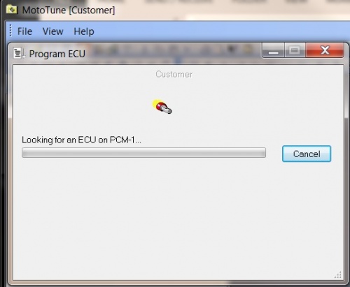
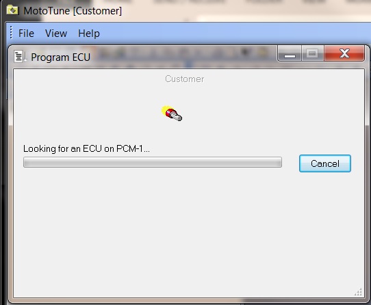
3. When the “Looking for an ECU” prompt appears in the dialogue box, turn on power to the ECU. The module must “wake-up” with the boot key or boot signal applied in order to force a reboot.
Note: The ECU must recognize the boot signal within 2-3 seconds of waking. Therefore, it helps to apply power first, begin programming in MotoTune, then immediately key on when MotoTune begins looking for the ECU.
To boot strap the following modules, make the following connections and follow the steps above.
HCM/GCM-0563-48 See also GCM/HCM Module Recovery document
- AN1,3,5: Pull to GND
- AN2,4,6,7-12: Pull to +5V
Note: For the GCM-0563-048-0802, the boot harness (analog sequence) must be used, not the boot key.
ECM48_563
- AN1 – AN6: Pull to +5V
- AN8: Pull to GND
- AN11 & AN12: Pull to +5V
GCM-0S12-024 (MCHI)
- AN1,AN2,AN4,AN5: Pull to +5V
- AN3, AN6: Pull to GND
ECM-0S12-024 (SECM)
- AN1,2,3,4,6,7: Pull to +5V
- AN5, AN8: Pull to GND
- Read the following: HCS12 Boot Cable
ECM-S12X-070
- AN1,AN4-6: Pull to +5V
- AN2,AN3, AN7: Pull to GND
To Use the Boot Key with the 128-pin module on the Desktop IO Simulator::Read the following 128-pin module boot key with IO simulator

