Uncategorized files
From MotoHawk
Jump to navigationJump to searchShowing below up to 250 results in range #1 to #250.
View (previous 250 | next 250) (20 | 50 | 100 | 250 | 500)
 10V58XVRsignal.jpg 717 × 514; 29 KB
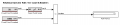
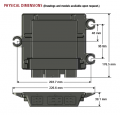 112 Dim.png 453 × 435; 46 KB
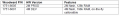
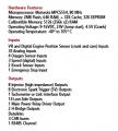 112 HW.png 322 × 357; 17 KB
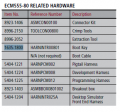
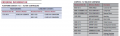 112 PN.png 740 × 220; 37 KB
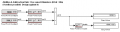
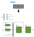
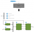
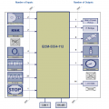 112 blockdiag.png 666 × 665; 153 KB
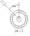 24 2 Crank.jpg 164 × 196; 5 KB
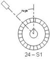 24 S1 Crank.jpg 154 × 182; 5 KB
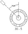 30 5 Crank.jpg 164 × 196; 6 KB
 32 2 Crank.jpg 154 × 182; 6 KB
 36T Crank.jpg 154 × 182; 6 KB
 36 1 Crank.jpg 164 × 196; 6 KB
 3X Crank.jpg 164 × 196; 4 KB
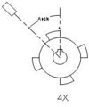 4X Crank.jpg 164 × 196; 5 KB
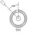 58X Crank.jpg 164 × 196; 6 KB
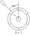 6+1 Cam.jpg 171 × 193; 6 KB
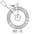 60 6 Crank.jpg 143 × 154; 5 KB
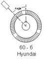 60 6 Hyundai Crank.jpg 154 × 182; 6 KB
 70 pin PWM.png 382 × 302; 73 KB
 70 pin pn.png 739 × 238; 34 KB
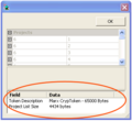
 800px-AboutToken2.png 193 × 106; 22 KB
 ADCAngleVectorDefinition.JPG 430 × 215; 16 KB
 ADCAngleVectorElement.JPG 428 × 178; 13 KB
 ADCAngleVectorReadyTrigger.JPG 199 × 109; 7 KB
 ADCAngleVectorStoppedTrigger.JPG 197 × 103; 8 KB
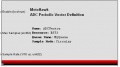 ADCPeriodicVectorDefinition.JPG 431 × 239; 15 KB
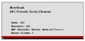 ADCPeriodicVectorElement.JPG 384 × 184; 11 KB
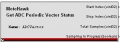 ADCPeriodicVectorStatus.JPG 350 × 124; 10 KB
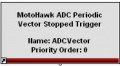 ADCPeriodicVectorStoppedTrigger.JPG 186 × 102; 6 KB
 ADCVectorDefnExampleFig.jpg 409 × 229; 19 KB
 AboutToken.PNG 1,380 × 900; 29 KB
 Abs time.jpg 56 × 42; 9 KB
 Absolute Override.PNG 169 × 36; 643 bytes
 Absolute Time.PNG 56 × 41; 400 bytes
 Acceleration.jpg 823 × 462; 34 KB
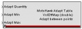
 Adapt Table.PNG 249 × 87; 2 KB
 Adapttable.jpg 253 × 91; 14 KB
 AddTableHS.png 16 × 16; 605 bytes
 Add Port.PNG 1,131 × 503; 162 KB
 Ain Read.PNG 327 × 115; 3 KB
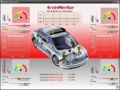 Amscreen.jpg 550 × 413; 91 KB
 An-in-3.png 472 × 276; 242 KB
 An-in-DRAW-2.png 77 × 487; 9 KB
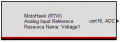
 Analog Input.PNG 262 × 105; 2 KB
 Analog Input Reference.PNG 262 × 94; 1 KB
 Analog Output.png 295 × 133; 3 KB
 AnnArborPicture.jpg 180 × 98; 6 KB
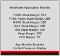 Application Monitor.PNG 213 × 197; 4 KB
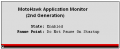 Application Monitor2ndGen.png 368 × 149; 3 KB
 Application Monitor Assertion.PNG 255 × 50; 1 KB
 Application Monitor Notification.png 255 × 51; 1 KB
 AsyncNonVolatile DataWrite.png 142 × 66; 854 bytes
 AverageRPMExample.png 703 × 411; 16 KB
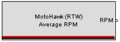 Average RPM.PNG 201 × 70; 1 KB
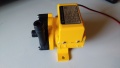 BLDCDriverSample TestMotor.jpg 3,264 × 1,836; 1.12 MB
 Banked injection.PNG 666 × 601; 18 KB
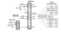
 Banked no cam coil config 4cyl.JPG 463 × 347; 31 KB
 Banked with cam coil config 4cyl.JPG 561 × 421; 41 KB
 Batched inj config 4cyl.JPG 487 × 365; 43 KB
 Batched with cam coil config 4cyl.JPG 463 × 347; 35 KB
 Bit order.png 577 × 63; 10 KB
 Block-parm1.png 374 × 485; 20 KB
 Bnum-02b.png 709 × 184; 3 KB
 Bnum-03b.png 712 × 200; 4 KB
 Bnum-04b.png 711 × 190; 4 KB
 Bnum-05b.png 714 × 150; 3 KB
 Bootkey Diagram.png 883 × 462; 74 KB
 Buffered EEPROM.JPG 405 × 218; 14 KB
 Build Time Date Stamp.PNG 189 × 59; 749 bytes
 CAM-3.png 472 × 276; 247 KB
 CAN-3.png 472 × 276; 246 KB
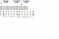
 CANByteOrder.png 500 × 208; 6 KB
 CANFilter.jpg 656 × 252; 52 KB
 CANNewBlocks.png 1,053 × 707; 259 KB
 CANRecSlotTrig1.jpg 187 × 109; 13 KB
 CAN Definition.PNG 272 × 196; 4 KB
 CAN Fault Status.PNG 233 × 57; 1 KB
 CAN Receive Slot Properties.PNG 445 × 195; 4 KB
 CAN Receive Slot Trigger.PNG 185 × 111; 2 KB
 CAN Send Interval Example.jpg 827 × 543; 45 KB
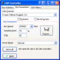 CANking controller bus parameters.PNG 334 × 335; 14 KB
 CANking controller bus stats.PNG 334 × 335; 15 KB
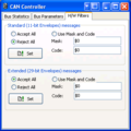 CANking controller filters.PNG 334 × 335; 14 KB
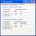 CANking controller filters mototune.PNG 334 × 335; 14 KB
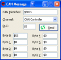 CANking message universal.PNG 238 × 234; 9 KB
 CANking message universal menu.PNG 640 × 96; 9 KB
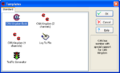
 CANking new project.PNG 459 × 275; 12 KB
 CANking output window error frames.PNG 573 × 332; 17 KB
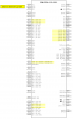
 CANking output window key.PNG 573 × 332; 12 KB
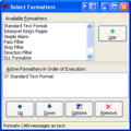 CANking select formatters.PNG 319 × 319; 13 KB
 CANking template.PNG 510 × 312; 12 KB
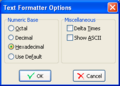 CANking test formatter options.PNG 253 × 182; 8 KB
 CCM1001 PCM0904 Delta.png 651 × 1,063; 55 KB
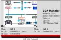 CCPCANHandler.png 395 × 261; 43 KB
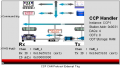 CCPCANHandlerTrig.png 468 × 265; 50 KB
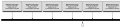 CCPDAQTriggerBlocksCR.png 886 × 197; 5 KB
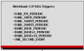 CCPDAQTriggers.png 341 × 209; 5 KB
 CCPSecSKCal.png 228 × 108; 2 KB
 CCPSecSKDAQ.png 228 × 108; 2 KB
 CCPSecTrigCAL.png 374 × 201; 2 KB
 CCPSecTrigCAL2.png 192 × 213; 3 KB
 CCPsec1.png 707 × 415; 5 KB
 CCPsec2.png 376 × 262; 3 KB
 CCS-ClientServices.jpg 734 × 711; 125 KB
 CCS CSVConverter.jpg 565 × 469; 34 KB
 CItH.png 504 × 393; 23 KB
 CSSstruct.jpg 477 × 225; 33 KB
 Calibration.PNG 166 × 48; 710 bytes
 Canfd bit order.png 1,694 × 220; 40 KB
 Canlogrecord.jpg 832 × 123; 23 KB
 Canlogrecordframes.jpg 761 × 98; 10 KB
 Canlogrecordstop.jpg 925 × 123; 24 KB
 Carbon Gauge small.PNG 746 × 741; 307 KB
 Ccs.jpg 400 × 395; 37 KB
 CcsERI.PNG 804 × 368; 48 KB
 Ccs Tree.jpg 251 × 196; 20 KB
 Ccs enable.jpg 421 × 347; 37 KB
 Ccs loadfile.jpg 338 × 127; 20 KB
 Ccs msg stats.jpg 723 × 388; 72 KB
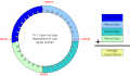
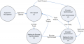
 Circular process.jpg 252 × 270; 25 KB
 CityID1.jpg 750 × 418; 64 KB
 CityID2.jpg 750 × 480; 67 KB
 Clear All Faults.PNG 149 × 49; 815 bytes
 Clear Fault.PNG 179 × 47; 690 bytes
 Cmd0.png 352 × 192; 6 KB
 Cmd3.png 670 × 107; 6 KB
 Cmd4.png 671 × 152; 9 KB
 Code Coverage.PNG 181 × 36; 2 KB
 Code Coverage Manager.PNG 333 × 58; 6 KB
 Component Input.PNG 166 × 36; 506 bytes
 Component Input.png 166 × 36; 506 bytes
 Component Instance.PNG 361 × 201; 44 KB
 Component Output.PNG 166 × 36; 532 bytes
 Component Output.png 166 × 36; 532 bytes
 Component Ports.png 586 × 327; 90 KB
 Component Target.png 560 × 348; 49 KB
 Component Target Encrypt Build.PNG 415 × 380; 55 KB
 Component Target Encrypt Entire.PNG 414 × 382; 56 KB
 Component Target No Encryption.PNG 413 × 381; 55 KB
 Connect1.png 618 × 168; 54 KB
 Connect2.png 326 × 476; 45 KB
 Connect3.png 776 × 417; 81 KB
 Constant Current Control Output.PNG 390 × 137; 3 KB
 Contl-core-icon1.jpg 22 × 26; 8 KB
 ControlCoreTaskExample.PNG 781 × 313; 26 KB
 ControlCoreTask Example1.PNG 833 × 228; 11 KB
 ControlCoreTask Example2.PNG 416 × 216; 6 KB
 ControlCoreTask Example3-1.PNG 602 × 202; 10 KB
 ControlCoreTask Example3-2.PNG 189 × 139; 3 KB
 ControlCoreTask Example3-3.PNG 187 × 143; 3 KB
 ControlCoreTask Example3-4.PNG 191 × 147; 3 KB
 ControlCoreTask Example4.PNG 629 × 473; 14 KB
 ControlCore Medium.gif 252 × 49; 6 KB
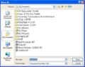
 Create-tkf-dongle0.png 205 × 195; 22 KB
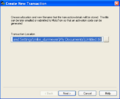
 Create-tkf-dongle1.png 376 × 203; 6 KB
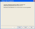
 Create-tkf-dongle1a.png 376 × 203; 7 KB
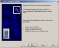
 Create-tkf-dongle2a.png 333 × 306; 11 KB
 CreateTKFReadme img 0.png 503 × 411; 23 KB
 CreateTKFReadme img 1.png 541 × 205; 11 KB
 CreateTKFReadme img 2.png 495 × 410; 10 KB
 CreateTKFReadme img 3.png 496 × 409; 12 KB
 CreateTKFReadme img 4.png 575 × 451; 139 KB
 CreateTKFReadme img 5.png 500 × 410; 11 KB
 CreateTKFReadme img 6.png 501 × 409; 22 KB
 CreateTKFReadme img 7.png 457 × 138; 8 KB
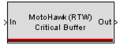 Critical Buffer.PNG 152 × 57; 915 bytes
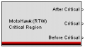 Critical Region.PNG 181 × 102; 2 KB
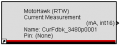 CurrentMeasurement.png 292 × 115; 2 KB
 Customize.png 224 × 37; 3 KB
 Cycle rpm.jpg 865 × 392; 80 KB
 Cylinder Knock PIPI Window Set.PNG 331 × 115; 2 KB
 Cylinder Knock Sync Window Set.PNG 331 × 117; 2 KB
 DB-ed-1.png 927 × 435; 23 KB
 DG-3.png 472 × 276; 246 KB
 DG-drwg-2.png 90 × 283; 10 KB
 DLM565 24.png 300 × 300; 129 KB
 DataCoherencyStrategy.PNG 652 × 175; 10 KB
 DataCoherency Example1-1.PNG 633 × 131; 7 KB
 DataCoherency Example1-2.PNG 365 × 116; 6 KB
 DataCoherency Example1.PNG 853 × 338; 14 KB
 DataCoherency Example1a.PNG 765 × 707; 53 KB
 DataCoherency Example1b.PNG 721 × 775; 71 KB
 DataCoherency Example1c.PNG 822 × 761; 73 KB
 Data Definition.PNG 139 × 62; 753 bytes
 Data Definition.png 139 × 62; 753 bytes
 Data Read.PNG 145 × 68; 861 bytes
 Data Reference.PNG 163 × 45; 679 bytes
 Data Write.PNG 152 × 67; 910 bytes
 Database Location Folders.PNG 331 × 521; 22 KB
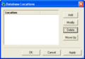 Database Locations.PNG 350 × 244; 8 KB
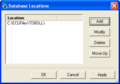 Database Locations with TDBDLL.PNG 350 × 244; 9 KB
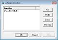 Databaselocations.jpg 358 × 246; 14 KB
 Datalog screen.JPG 300 × 213; 24 KB
 Debug Counter.PNG 177 × 57; 842 bytes
 Debug Counter Evaluated.PNG 176 × 57; 920 bytes
 Debug Counter Evaluated2.PNG 176 × 57; 789 bytes
 Debug Counter Evaluated Triggered.PNG 176 × 61; 968 bytes
 Debug Counter Triggered.PNG 176 × 60; 866 bytes
 DeleteHS.png 16 × 16; 743 bytes
 Delta Time.PNG 56 × 36; 323 bytes
 Delta Time.png 56 × 36; 323 bytes
 DeskSim-2.png 672 × 472; 402 KB
 Desktop01.png 516 × 398; 318 KB
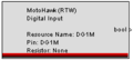 Digital Input.PNG 215 × 97; 2 KB
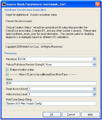
 Digital Input Parameters.PNG 451 × 611; 24 KB
 Digital Input Reference.PNG 215 × 81; 1 KB
 Digital Output.PNG 215 × 81; 1 KB
 Disc-in-param.jpg 446 × 524; 77 KB
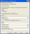 DiscreteOutput Parameters.jpg 450 × 501; 45 KB
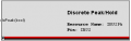 DiscretePeakHold.PNG 347 × 111; 2 KB
 Display Debug Variables.PNG 238 × 63; 927 bytes
 Display Variable Event Boolean.PNG 170 × 43; 627 bytes
 Display Variable Event Function Call.PNG 169 × 43; 538 bytes
 Double to Fixed Point.PNG 52 × 28; 388 bytes
 DualPSP.png 519 × 274; 6 KB
 ECM-5644A-112-048-1202-xD.jpg 497 × 689; 114 KB
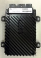
 ECM024.jpg 480 × 480; 17 KB
 ECM048.jpg 480 × 480; 17 KB
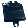
 ECM070.jpg 375 × 375; 11 KB
 ECM080.jpg 480 × 480; 18 KB
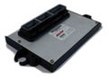
 ECM112.jpg 480 × 480; 20 KB
 ECM128.jpg 480 × 480; 20 KB
 ECM24 pn.png 688 × 236; 22 KB
 ECM48555 pn.png 703 × 227; 43 KB
 ECM48563 pn.png 702 × 218; 38 KB
 ECM5634M-70.jpg 768 × 768; 49 KB
 ECM80 Hardware.PNG 289 × 269; 21 KB
 ECMOH1.png 786 × 107; 56 KB
 ECM OH1.png 1,161 × 423; 24 KB
 ECU555-48.jpg 93 × 89; 2 KB
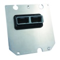
 ECU555-80.jpg 168 × 120; 19 KB
 ECUHCS12-uCHI.jpg 64 × 53; 4 KB
 ECUcircuitry.png 200 × 186; 12 KB
 ECUs.PNG 851 × 515; 304 KB
 EST-3.png 472 × 276; 243 KB
 EZGage0.jpg 240 × 224; 14 KB
 EZSlider.jpg 301 × 37; 9 KB
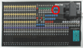
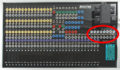
 EasYgen800.jpg 696 × 504; 46 KB
 EasYgen800 back.jpg 480 × 360; 38 KB
 EncoderState BubbleFig.png 630 × 330; 18 KB
 Encoder Angle.PNG 199 × 70; 1 KB
 Encoder Angle Extrapolation.PNG 200 × 69; 1 KB
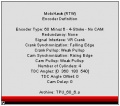
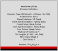 Encoder Definition.PNG 297 × 262; 5 KB
 Encoder Fault.PNG 200 × 70; 1 KB
 Encoder Fault Trigger.PNG 185 × 80; 1 KB
 Encoder Phase.PNG 201 × 71; 1 KB
 Encoder State.PNG 200 × 71; 1 KB
 Encoder State Trigger.PNG 186 × 81; 1 KB
 Encoder TDC Offset.PNG 200 × 69; 1 KB
 Encoder avg rpm.jpg 200 × 73; 12 KB
 Encoder def.jpg 299 × 263; 28 KB


