
MotoHawk OBD Fault Manager
This block defines an instance of an On Board Diagnostics (OBD) Fault Manager. It is required if any of the OBD Fault Manager Blocks are to be used in a model.
Block ID
OBD Fault Manager
Library
MotoHawk OBD Fault Manager
Description
OBD Quick Access
- OBD Fault Manager Block Parameters
- OBD Fault Manager Condition Summary
- Including OBD Fault Manager functionality in your Model
OBD Fault Manager Overview
What is OBD?
On Board Diagnostics (OBD) refers to emission regulations. Most governments have some emission compliance, or are heading in that direction. There is a good chance that a developer creating an application that runs on the highway will require OBD certification. Such an application would need to be “OBD Compliant” to a set of regulations.
OBD-Regulations depend on the location or country, as well as the market so the OBD-Compliance of an application is driven by where it will be used. Most countries have active or pending regulations, so it is important to understand where the application will be used and what the OBD-requirements are. There are also differences in OBD requirements based on the market. For example on-highway heavy duty applications have different requirements relative to light duty vehicles.
As a mechanism for obtaining OBD certification, many OBD regulations exist that determine what fault conditions are required. Examples of these include:
- E-OBD – These regulations are enforced in Europe. Other countries have also adopted slight variances of this regulation as well. There are also different versions of the E-OBD standard which is where the term “Euro 4” and “Euro 6” originate.
- OBD II – This is enforced in the United States by the EPA and CARB. Other countries have adopted “lighter” versions of this regulation.
- WWH – This is otherwise known as “World Wide Harmonized” OBD. In general, this is an effort to standardize OBD regulations between countries.
OBD's Four Principle Aspects
Emission Levels
Perhaps the most important part of OBD is the emission requirements and this aspect of OBD is the driving force behind the other three aspects. The application team must know which countries will employ the end product and what is specifically required for OBD compliance in those countries. Emission controls can also change from year to year, so the application team needs to be aware of how the emission requirements will change.
Fault Storage
A standard method of tracking and organizing faults is required to enforce the emission control rules. In addition to fault storage, other information is required for some regulations and not for others. The primary purpose of the OBD Fault Manager is to assist with this aspect of OBD. It can track fault conditions and also track extra data that is associated with a fault. There are special data stores called Custom Fields that will expand and contract with the number of faults present in the application. It allows the application to track information that is required for some regulations. For example, tracking “Number of Hours Since DTC was Set”.
Scan Tool Interface
All OBD regulations have communication protocols necessary for extracting the OBD information from an OBD-compliant module. J1939, ISO15031 (a.k.a. SAEJ1979), and ISO14229 are examples of
protocols that are OBD-compliant. Similar to the statements above, different OBD regulations require different protocols, so the application team needs to be aware of the required protocol(s).
The secondary purpose of the OBD Fault Manager is to provide seamless integration with the various OBD scan tool protocols. MotoHawk supports two blocksets that can assist the application
developer to report OBD faults via a scan tool.
- J1939 Block Set
- ISO15765/UDS Block Set
Certification Process
The certification process is the verification that OBD applications are obeying the rules. There are some processes in place to prevent OBD applications from breaking the rules. The regulators will require that certain documents are in place and that certain procedures are followed. In summary, most procedures are meant to assure that the vehicles on the road are the same as the vehicles that are used for emissions and scan tool testing.
What is the OBD Fault Manager
MotoHawk's OBD Fault Manager block set are a set of flexible blocks that can assist application developers in designing OBD compliant systems of differing requirements.
Note that by itself the use of the OBD Fault Manager does not satisfy OBD requirements. It is just a set of building blocks that will allow the creation of an OBD compliant system. An OBD infrastructure needs to be built into the application.
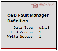
The OBD Fault Manager definition block defines an instance of an On Board Diagnostics (OBD) Fault Manager. It is required if any of the OBD Fault Manager Blocks are to be used in a model. The block defines global OBD Fault Manager settings such as default Instrumentation access levels, underlying suspected counter widths, and the set of allowed fault action conditions that are used with blocks like the OBD Fault Action Route Definition block.
OBD Fault Manager Concepts
OBD Fault Manager has
- A “Drive Cycle” concept.
- Separate “Emissions Related” and “Non Emissions Related” faults. Some faults impact emissions while others do not. They are treated differently throughout the OBD scan tool and condition management logic based on this distinction.
- A Pending condition. The pending condition is very similar to the “Active” state in the Classic Fault Manager. The difference is that the Pending condition is NonVolatile in the OBD Fault Manager. Pending requires the concept of “Drive Cycle” to exist as this defines how a fault becomes Confirmed.
- A Confirmed condition that is TRUE when a monitor is known to be failing.
- A Permanent condition.
- A way to selectively clear conditions.
- A “Global Enable”. In the UDS protocol, the ability to “turn off” faults from being set is needed. If the other modules on the system are in flux, such as when they are being programmed, then the other modules should not record faults. This helps to prevent false failures.
- The ability to more easily implement communication protocol with scan tools.
- The ability to define significantly more faults in the application.
- A built in parameter called FaultTest_<FaultName> which can be used at runtime to set an individual fault to suspected, even if the logic feeding the suspected status is not active.
OBD Fault Conditions
The OBD Fault Manager supports 13 fault conditions that are a mixture of NonVolatile and Volatile. NonVolatile fault conditions do not "self heal" and require intervention by the application to clear. This is called bookkeeping and usually occurs at the end of the drive cycle.
| Name | Default Storage Type | Clear Condition | Description |
|---|---|---|---|
| Suspected | Volatile | The fault definition input is false (fault not suspected). | Reflects the current status of the fault assertion condition (suspected input of the Fault Definition block or the Fault Set block). It can be prone to noise and so an X of Y style filter is used to qualify whether a fault is Suspected or Pending. |
| Pending | NonVolatile | Cleared at the end of the drive cycle when the Mark To Clear block parameter is set to Pending and the inhibit input is zero at least once during the drive cycle. Execution of the fault clear block can also clear this condition. |
TRUE whenever X of Y samples is TRUE (i.e. the fault was suspected at least X out of Y samples). X and Y defaults for each fault are set via the Fault Definition block. |
| Confirmed | NonVolatile | Cleared at the end of the drive cycle when the Mark To Clear block parameter is set to Confirmed and the inhibit input is zero at least once during the drive cycle. Execution of the fault clear block can also clear this condition. |
A fault is considered Confirmed TRUE if the fault has had a Pending condition of TRUE for at least X of Y "Drive Cycles".
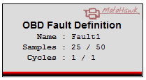
For example, if the Drive Cycles and Total Drive Cycles are set to 1 and 1 then
the fault is a 2 trip fault. After the fault becomes Pending, if it is detected again in the next drive cycle the fault will become confirmed
immediately after the fault is detected. "Drive Cycle" defaults for each fault are set via the Drive Cycles and Total Drive Cycles options of the Fault Definition block. |
| Ready | NonVolatile | Cleared at the end of the drive cycle when the Mark To Clear block parameter is set to Ready and the inhibit input is zero at least once during a drive cycle. Execution of the fault clear block can also clear this condition. | TRUE when the filter method has executed to completion (i.e. reached Y samples). It implies that the diagnostic associated with this fault has run to completion. |
| Failed This Drive Cycle | Volatile | Cleared at the end of the drive cycle. | TRUE when the fault has attained the Pending status for the current drive cycle. |
| Test Complete This Drive Cycle | Volatile | Cleared at the end of the drive cycle. | TRUE when the filter method has executed to completion (i.e. reached Y samples). Similar to Ready except it is volatile rather than NonVolatile. |
| MIL Request | NonVolatile | Cleared at the end of the drive cycle when the Mark To Clear block parameter is set to MIL Request and the inhibit input is zero at least once during a drive cycle. Execution of the fault clear block can also clear this condition. |
A fault that has been configured as emissions-related and has a Confirmed condition of TRUE will set
MIL Request to TRUE. Intended to assist in MIL (Malfunction Indicator Light) illumination. The fault manager does not directly control a module output. Instead it provides a mechanism via the MIL Request condition that can be used to signal the application when MIL illumination should occur. |
| Previously Active | NonVolatile | Cleared at the end of the drive cycle when the Mark To Clear block parameter is set to Previously Active and the inhibit input is zero at least once during a drive cycle. Execution of the fault clear block can also clear this condition. | TRUE if a fault was Confirmed TRUE and then transitioned to FALSE. |
| Permanent | NonVolatile | Cleared at the end of the drive cycle when the Mark To Clear block parameter is set to Permanent and the inhibit input is zero at least once during a drive cycle. Execution of the fault clear block will NOT clear this condition. | The Permanent condition is similar to Confirmed except that the condition is only set TRUE if the fault is specified as Permanent (a fault definition option). |
| Test Failing | Volatile | A detection cycle that does not detect the fault. | Reports the most recent filter method result. Behavior is similar to Pending except it does latch. |
| Test Failed Since Last Clear | NonVolatile | Execution of the fault clear block can clear this condition. | TRUE if the fault has failed since a fault clear has occurred. |
| Failed Last Drive Cycle | NonVolatile | Clears as the end of the current drive cycle if a fault did not occur. | TRUE if the fault failed on the previous drive cycle. |
| Test Failed Since Key Cycle | Volatile | Cleared at the end of the key cycle when the Key Cycle Complete block executes. Execution of the fault clear block can also clear this condition. | TRUE if tests have failed in the current key cycle. Latches until the current key cycle is complete. |
OBD Memory Storage Considerations
The OBD Fault Manager generates code to cache the faults in a memory-efficient manner. The Memory Storage Tab may be used to move some fault conditions and basic constructs to NonVolatile memory. This is useful when the definition of a Drive Cycle will span power cycles. <\p>
Including OBD Fault Manager functionality in your Model
OBD Fault Manager Definition Block
To support the OBD Fault Manager an OBD Fault Manager Definition block must exist in the model. This block defines an instance (of which there can be only one) of an On Board Diagnostics (OBD) Fault Manager. Defining more than one will result in a Simulink Update error.
OBD Fault Definition Block
Each fault in the OBD system needs to be defined via an instance of the OBD Fault Definition block. This block defines various attributes for the fault beyond just its name including whether it is permanent, whether it uses an X of Y style filter and drive cycles configurations.
OBD Fault Mark To Clear Block
The OBD Fault Mark To Clear block is used for bookkeeping. A boolean input signal is used to configure whether a particular fault condition is to be cleared at the end of the drive cycle.
![]()
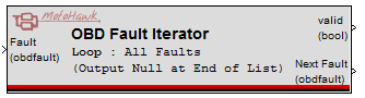
OBD Fault Iterator Block
The OBD Fault Iterator block iterates through the OBD Fault Definitions being monitored by the OBD Fault Manager that meet a specified condition. Thus this block could be used (say) to iterate through all the faults that are pending or confirmed. The block can also be used to iterate through all faults in the system.
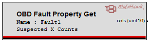
OBD Fault Property Block
The model can access properties of an OBD fault at runtime such as whether the fault is permanent or the current value of the Suspected X Counts in order to make decisions or influence behavior via the OBD Fault Property block.
Fault Trigger Blocks
There are several blocks that trigger based on status of the OBD Fault Manager.
- The end of a drive cycle can be triggered by the OBD Drive Cycle Complete block.
- The Clear all Faults block will clear all faults (except faults that are permanent - these can only be cleared by the OBD Fault Mark To Clear) and resets the counters. The block can be configured to clear all, or only emission related faults.
- The OBD Fault Activity Trigger block executes when the fault meets the set criteria.
OBD Drive Cycle Complete Block
The OBD Drive Cycle Complete block triggers the end of a Drive Cycle, which is a critical unit of measure in OBD and will likely result in several events occurring.
Block Parameters
Main Tab
| Parameter Field | Values | Comments/Description |
|---|---|---|
| Read Access Level | 0-8 | Sets security level 1 lowest, 8 highest, for user access to read value. A setting of zero indicates unsecured access is allowed. |
| Write Access Level | 0-8 | Sets security level 1 lowest, 8 highest, for user access to write value. A setting of zero indicates unsecured access is allowed. |
| Instrumentation Group | Alpha-numeric text, single-quote enclosed | Instrumentation folder name and hierarchy. Use the "|" character between folder names to delineate subfolder structure |
| Suspected X/Y Data Type | uint8 or uint16 | X and Y counter datatype. The larger the data type, the more counts can be accumulated at the expense of memory use |
Fault Action Tab
| Parameter Field | Values | Comments/Description |
|---|---|---|
| Fault Action Visibility | Dropdown |
Select the method that will be used to define what fault action conditions are legal for this application. Some applications don't utilize all possible fault conditions. Exposing unused conditions can complicate calibration and documentation. This option allows the set of fault action conditions that are to be made visible to instrumentation to be defined. Thus an application that does not have the concept of a MIL Request need not expose this as an allowed fault action condition. |
| Allowed Fault Action Conditions | Cell array of strings, Expression |
Only visible when Fault Action Visibility selects the 'Specify allowed conditions with edit dialog'. The value entered should be a cell array of strings with values for the desired conditions that shall allow fault actions. Typically this option is only used when a work space variable is to be used to specify the values. A cell array that was to specify all possible conditions as being allowed would be as follows: {'Suspected','Pending','Confirmed','Ready','Failed This Drive Cycle','Test Complete This Drive Cycle','Previously Active','MIL Request','Permanent','Test Failing','Test Failed Since Last Clear','Failed Last Drive Cycle','Test Failed Since Key Cycle'}. |
|
Suspected Pending Confirmed Ready Failed This Drive Cycle Test Complete This Drive Cycle Previously Active MIL Request Permanent Test Failing Test Failed Since Last Clear Failed Last Drive Cycle Test Failed Since Key Cycle |
Checkboxes |
Check to include this condition in the set of allowed fault action conditions. Only visible when Fault Action Visibility selects the 'Specify Allowed Conditions with checkboxes'. |
Memory Storage Tab
| Parameter Field | Values | Comments/Description |
|---|---|---|
| Failed This Drive Cycle | string, Expression | Either 'Volatile' or 'NonVolatile' to designate the appropriate memory type. |
| Test Complete This Drive Cycle | ||
| In Use Performance Monitor (Numerator/Denominator) Occured This Drive Cycle | ||
| In Use Performance Monitor General Counter Occured This Drive Cycle | ||
| Fault Test | string, Expression | Either 'Constant', 'NonVolatile', or 'Volatile' to designate the appropriate memory type. |
| Permanent Status | string, Expression | Either 'Constant' or 'NonVolatile'to designate the appropriate memory type. |
| Emissions Related | ||
| Suspected X&Y Count | ||
| Drive Cycle X&Y Count | ||
| Fault Action Route (assignment and condition) |