Difference between revisions of "112-pin Module Family"
From MotoHawk
Jump to navigationJump to searchm (Converted the Differences link (was link to a PDF) to an inline image) |
m (GCM-5554-112-1001: converted the linked image's underscores to spaces) |
||
| Line 41: | Line 41: | ||
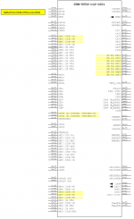
Differences between the ECM-5554-112-0904 and the GCM-5554-112-1001 are also shown in the diagram below. | Differences between the ECM-5554-112-0904 and the GCM-5554-112-1001 are also shown in the diagram below. | ||
| − | [[Image: | + | [[Image:CCM1001 PCM0904 Delta.png|150px|Differences]] |
1751-6456 (PROD) | 1751-6456 (PROD) | ||
Revision as of 06:36, 18 March 2015
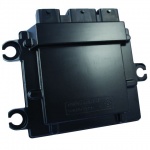
There are two ECUs in the 112-pin family - the ECM-5554-112-0904 (PCM-09) and the New ECM-5644-112 (ECM-OH).
ECM-5554-112-0904
Hardware Features
- Microprocessor: Motorola MPC5554, 80 MHz
- Memory: 2MB Flash, 64K RAM, + 32K Cache, 32K EEPROM
- Calibratible Memory: 512k (256k x2) RAM
- Operating Voltage: 9-16VDC, 24V (Jump start), 4.5V (Crank)
- Operating Temperature: -40° to 105° C
Inputs
- VR and Digital Engine Position Sensor (crank and cam) Inputs
- 33 Analog Inputs
- 4 Oxygen Sensor Inputs
- 3 Speed (digital) Inputs
- 2 Knock Sensor Inputs
- 1 Emergency Stop Input
Outputs
- 8 Injector (high impedance) Outputs
- 8 Electronic Spark Trigger (5V) Outputs
- 1 Tachometer or Link Interface Output
- 14 Low Side Outputs
- 1 Main Power Relay Driver Output
- 2 H-Bridge Outputs
Datalinks
- 3 CAN buses
- 1 RS485 Channel
GCM-5554-112-1001
The 112 pin General Control Module is the same as the ECM-5554-112-0904 above except with engine related IO replaced by analog inputs for general control purposes.
The following are the changes from ECM-5554-112 to GCM-5554-112:
- pins EST1 to EST8 change to AN34 to AN41 (3k-ohm pull-down, with a diode drop between pull-down resistor and ground).
- AN1, AN2, AN3, AN26, AN27, AN28 change from 51.1k pull-down to 220k-ohm pull-down.
- GCM-5554-112 does not populate the internal CAN3 termination: all 3 CAN buses are un-terminated internally.
Differences between the ECM-5554-112-0904 and the GCM-5554-112-1001 are also shown in the diagram below.
1751-6456 (PROD) 1751-6457 (DEV)
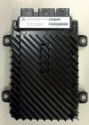
ECM-5644-112 ECM-OH
This is our newest module! Check out features and additional information on the ECM-OH wiki page.
These are Preliminary Specifications and subject to change.
Hardware
- 112-pin platform
- Main micro: MPC5644A, 120 MHz
- Auxiliary micro: S12G48, 24MHz
- Memory: 2M flash, 128K RAM, 32K external serial EE; S12G: 48K flash, 4k RAM, 1.5K EE,
- Calibratible micros: MPC5644A, 4M flash, 192K RAM; S12G128, 128k flash, 8K RAM, 4K EE
- Operating Voltage: 8–32 Vdc,36 V (jump start), 5.5 V (crank)
- Operating Temperature: –40 to +105°C
Inputs
- VR or digital crank position sensor
- VR or digital cam position sensor
- Up to 31 analog inputs
- Up to 4 switching oxygen sensors
- Up to 2 wide-range oxygen sensors
- 2 knock sensors
- Up to 6 speed inputs
Outputs
- 8 injector drivers (6 peak/hold capable)
- 8 ignition coil drivers or spark timer outputs
- 1 tachometer driver
- Up to 19 low-side drivers (1 w/current sense)
- 1 main power relay driver
- 2 H-bridge drivers w/current sense
- 3 sensor supplies (2-5V, 1-12V)
Communications
- 3 CAN 2.0b buses
- 1 RS-485 bus


