ToolKit Custom HMI Software
Contents
ToolKit Customer HMI Software
This Article is Being Created, and is not Finished or Complete at this Time... Stay Tuned.
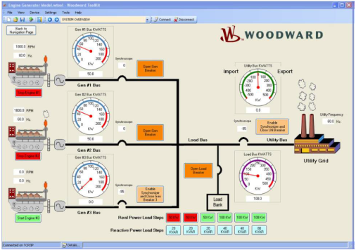
Toolkit is a Woodward Windows based software program used to create standard or custom HMI (Human Machine Interface) software programs for use with Woodward products. The created HMI programs can be used as graphical engineering workstations, configuration tools, or operator control panels for users to directly interface with Woodward products.
The images shown on this tool screen are engines and generators, but the user can select their own images to suit their particular application for the HMI tool.
Toolkit supports these primary functions:
- Monitoring and Changing Device Parameter Values: A ToolKit tool may contain one or more pages of parameters for troubleshooting or tuning procedures.
- Settings Management: ToolKit can load or save all calibration settings to and from the device. This feature allows a user (e.g., fleet owner, distributor, packager) to save all settings from one device and load the same settings to other devices. Saved settings files can be modified offline and compared for differences.
- Trending: ToolKit provides a basic trending tool that graphically plots data to the screen. A trend graph can be saved to a spreadsheet compatible file and used for further analysis.
- Custom Tool Design: Device parameters can be dragged and dropped in a visual environment to create custom pages within a tool file. There are several components that can be used to represent the device parameter such as gauges, drop downs, text, etc. The Developer license is required to be able to create and design custom tools.
- Application Program Loading: ToolKit provides services to load a new application program to the device.
- Not supported on all hardware
- Not supported on all hardware
- Toolkit is a Platform for creating tools and not the tool itself.
Product Specification
The Woodward product specification (manual) for Toolkit is found on Woodward.com, under Support --> Product Specifications.
03366 - ToolKit Custom HMI Software from Woodward product specification
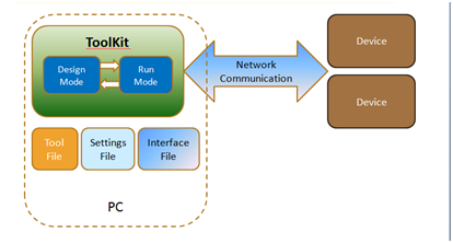
Toolkit Modes – Design Mode and Run Mode
Design Mode (Used to create an HMI Tool)
Toolkit can be used in Design Mode to design HMI interfaces with charts, tables, text windows, gauges, etc. The Tool file can then be saved (.wtool). A tool must be created in Design Mode first, before device parameters can be displayed or calibrated. All parameters (components) to be displayed or calibrated must be added to the tool.
Run Mode
Once a tool is created, Toolkit can then be used in Run Mode to Display parameters, calibrate parameters, etc from the Device. Calibration or Settings are stored in a Settings file (.wset). Toolkit can also connect to multiple devices (ECU’s, Actuators, etc) with one tool file.
A Toolkit Developer License is required to use Design Mode.
Licensing
Toolkit has two licenses.
Basic Runtime License
The ToolKit Basic Runtime license is included free of charge in the ToolKit download. It allows users the ability to work with existing ToolKit-created tools (.wtool) to configure, calibrate, monitor, and troubleshoot their Woodward-based product.
Developer License (Design Mode)
The ToolKit Developer license (part number 8928-5016) allows users access to advanced features in the following functions: monitoring and changing device parameter values, settings management, and trending, plus the ability to create and edit custom ToolKit tools.
The Toolkit Developer license is sent as a code after ordering 8928-5016 (check the invoice). The code will provide one Node-Locked Toolkit Developer License. When Toolkit is first launched, the user will be prompted to enter the license code, or License Authorization can be selected under the Settings Pull Down menu. Toolkit is not licensed on the MotoHawk/MotoTune dongle.
If you purchase a Toolkit Developer License (8928-5016) and do not receive a code, check your invoice for a Serial Number or contact your Customer Support Representative.
MotoHawk Blocks required for use with Toolkit
ToolKit connects with the ECU (device) by XCP. If you are creating a MotoHawk model that will be used with Woodward ToolKit, the following MotoHawk Blocksets are required:
Links to help for current versions of the blocks are found from the MotoHawk help table of contents.
Summary
To Develop a Motohawk application that uses Toolkit, the application developer needs:
- Toolkit Design Mode
- Node Locked License.
- CSR (Customer Service Representative) emails a code upon purchase (or on the invoice)
- XCP Slave Blockset
- Included as part of MotoHawk, and blockset must be used in the MotoHawk Model.
- Blockset is used in the MotoHawk model to enable communication with XCP protocol
- Whether or not reprogramming by ToolKit is supported per module is listed in Modules Supporting XCP
- Toolkit Integration Blockset
- Included in MotoHawk, and blockset must be used in the MotoHawk Model.
MotoHawk can be downloaded from Woodward's main website, Woodward.com, but requires a license on the dongle to use.
Where to Download Toolkit and Required Blocksets
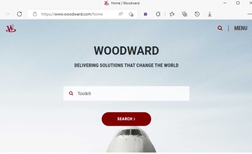
Toolkit is downloaded from Woodward's main website, Woodward.com.
Enter 'Toolkit' in the search box
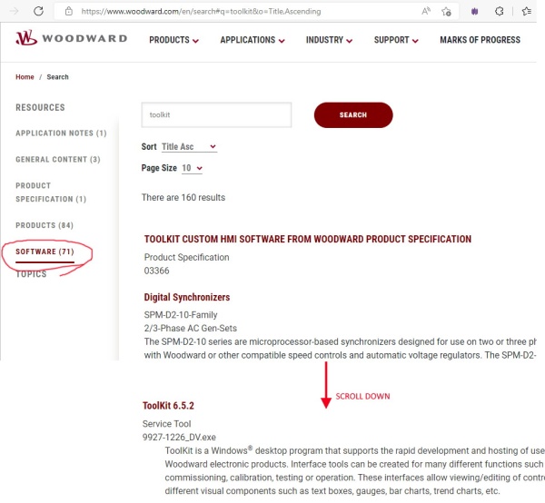
Filter by selecting 'Software' (under Resources on left side of page)
Scroll alphabetical results down to 'T' to find the Toolkit application to download
The MotoHawk Application
Woodward XCP Blockset
The application connects to Toolkit via the XCP, so XCP protocol must be defined in the model. The XCP blockset can be found in the main MotoHawk library under Protocols->XCP Slave Blocks, but is also supported using the legacy Woodward Custom XCP Slave blockset. These can be used to implement XCP protocol for communication with Toolkit, or any other 3rd party XCP calibration tool.
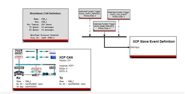
The below screenshot shows a sample model utilizing the MotoHawk Custom XCP Slave blockset.
Woodward Toolkit Integration Blockset
In addition to the XCP blockset, MotoHawk -> Protocols -> Toolkit Integration blockset or legacy Woodard Custom Toolkit Integration blockset is used in the MotoHawk model in order to build the Toolkit SID and WAPP file, and to define the Toolkit Event Manager.
Toolkit SID File A SID file is the Toolkit equivalent to the a2l file or the MotoTune DLL. It defines the tool interface between the target and Toolkit.
Toolkit WAPP File The WAPP file combines the SID, softboot, and application. This format is used by Toolkit when loading an application into a target. This file is not necessary if a tool other than Toolkit is used for the flashing process.
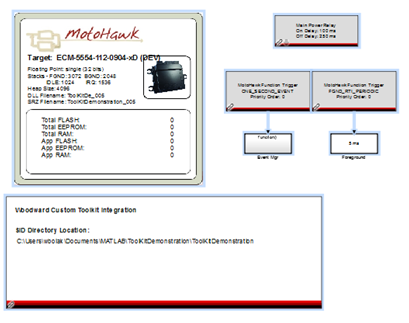
The Toolkit Integration Definition block shown below defines the parameters needed to build the .SID and .WAPP files which Toolkit uses to connect to and program the device.
Event Manager
Event Manager is a fault-reporting mechanism that is specific to Toolkit. It is an optional feature to display fault data.
It is not required.
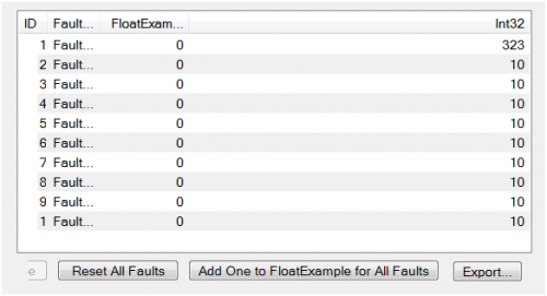
An example is shown below:
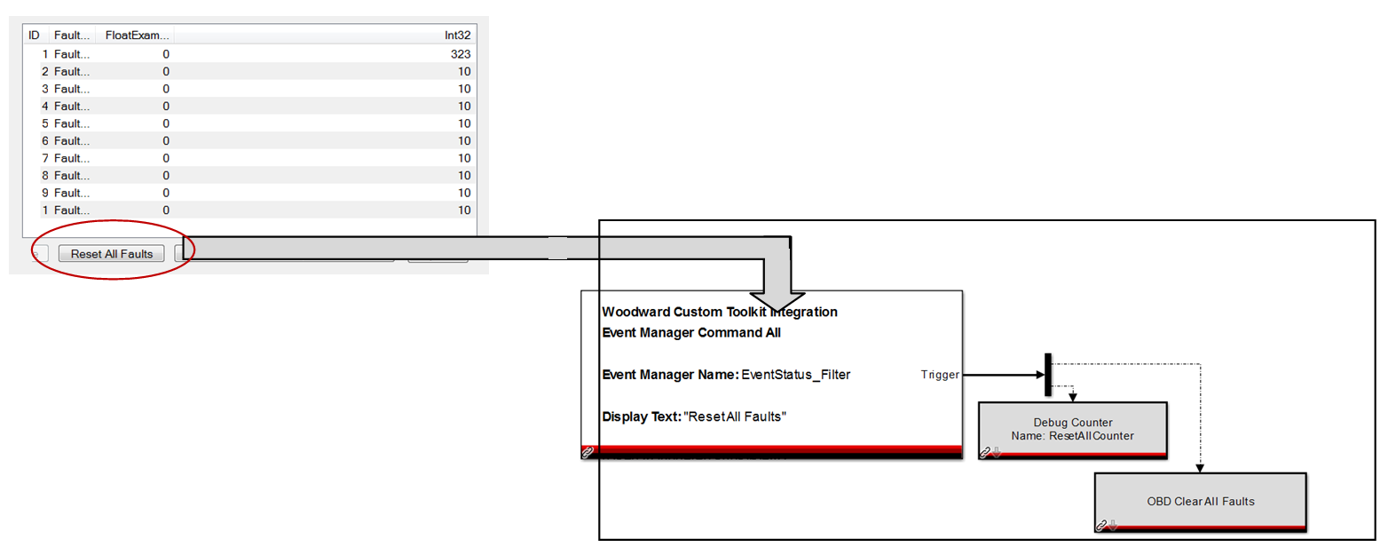
The Event Manager contains a number of rows where each row corresponds to a single fault. By default, the fault ID and Name are displayed. Additional columns such as fault state can also be displayed. Whether a particular fault appears is determined by the filter function. Action buttons such as ‘Reset All Faults’ can also be added to the Event Manager, and tied to execution of a particular action in the application model.
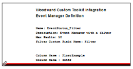
Each Toolkit Event Manager is defined in the MotoHawk application though a Toolkit Event Manager Definition Block.
The columns that are displayed in the Toolkit Event Manager are defined by an .m file which is referenced by name by the Event Manager Definition block (similar to the .m file for CAN message definition). See the html help for the Event Manager Defintion block and the attached example for more details.
Note: The Toolkit Event Manager can only be used with the MotoHawk OBD Fault Manager. The Event Manager Filter references the Custom field of the OBD fault. Models using the Classic fault manager can be used with Toolkit; however, the Event Manager mechanism cannot be used.
The Event Manager also features Action buttons such as Reset All Faults shown above. These Action buttons are enabled in the MotoHawk application through the Event Manager Command One and Command All Trigger Blocks. Command One is tied to a particular OBD fault, while Command All is executed for all faults in the Event Manager.
The below example adds the Reset All Faults button to the EventStatus_Filter Event Manager in Toolkit. When the user clicks the ResetAll Faults button, the logic triggered from the Event Manager Command All block is executed. As shown below, the OBD faults are cleared and the counters reset in the application.
The MotoHawk model can define multiple instances of Event Managers that can then be added to the Toolkit Tool.
Creating a New Tool in ToolKit
You can create a new tool (.wtool) file on-line or off-line with the device. The Tool Designer windows allow the user to create or edit a tool. Before an end user can display or calibrate real time data, a tool (.wtool) needs to be created. A new tool must be opened in Toolkit along with the .SID file for the device(s). Once the tool is created (a Toolkit Developer license is needed for this), other users can open and interface with the tool for real time display and calibration of the device.
When the MotoHawk model with the Toolkit Integration Block is built, the build will create a .SID file. This is similar to an A2L or .dll file. Toolkit will need to be able to locate the SID file from your MotoHawk build. Place the SID file from the build into a directory location of your choosing.
Open a New Tool
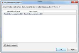
In Toolkit, Choose File -- Open a New Tool. Select the .SID File location to define the directory location of your SID File from the MotoHawk build. This .SID file will be associated with your new tool file. The display and calibration values from your MotoHawk application will be available as ‘Components’ in Toolkit and can be added to the tool as gauges, charts, text, tables, etc.
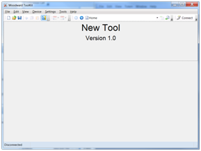
Select your SID file, click OK. SID File Locations can be used to add additional directory paths to the SID files. A new Tool will open to the Home Page.
Home Page
The Home Page summarizes the purpose of the Tool. No components are added to this page (a component is a text window, gauge, chart, table, etc.) that has been added to the Tool. The home page will display if no connections are available. The properties of the Home Page can be changed in design mode, under properties.
Operating Modes
The Ruler/Triangle Designer Icon Toggles Toolkit between Run and Design Modes. (Developer license is required for Design Mode).
Design Mode
Design Mode is where the user designs and saves the Tool file. The features of the HMI are defined. Components such as text windows, tables, gauges, buttons, are added to the Tool and configured in Design Mode. Some run-time data can be displayed when connected, however, Design Mode is intended for static configuration.
Run Mode
Run Mode is used for on-line display, charting, calibration, etc of the device (ECU). The Tool that was developed in Design Mode is opened and used with the device. The interface of the tool cannot be altered in Run Mode.
Select the Design Mode to open the Design Tools window and begin creating/editing the tool.
Design Tools Window
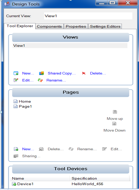
The Design Tools Window allows the Toolkit Tool Developer to create custom tools. The Design Tools window consists of 4 tabs, Tool Explorer, Components, Properties, Settings, and Settings Editor.
Tool Explorer – Toggle to design mode (ruler/triangle icon) to open the Tool Explorer
The Tool Explorer is the first tab and allows the tool developer to add Views, Pages, or Devices to the tool.
Pages
Each Tool (defined by the .Tool file and created in Design Mode) can have multiple pages. The user navigates from page to page in their view using the page navigation pulldowns shown below.
Devices
Pages can be Added, Configured, and Associated with a particular Device (ex. an ECU or actuator) in the Design Tools Explorer.
Components
The next tab in the Design Window is Components. Display and Calibration Data is added to a page/view in the tool by Components. Components are guages, text boxes, charts, etc that display or allow calibration of real time data in the Tool. After defining the initial views, pages, and devices for the Tool, select the Components Tab in the Design Tools Window. Display and Calibration values from the model will then be shown in the Components Tab. The structure will match the MotoTune Group Strings defined in the model.
Components are not related to MotoHawk Components.
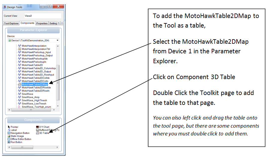
Example 1: Adding a 2D Lookup Table as a Component to a page
The 2D table is then dropped onto the page. The table name and axes labels can be configured by clicking on the properties arrow on the table.
Note: values will only be displayed if the tool is connected to the device (on-line).
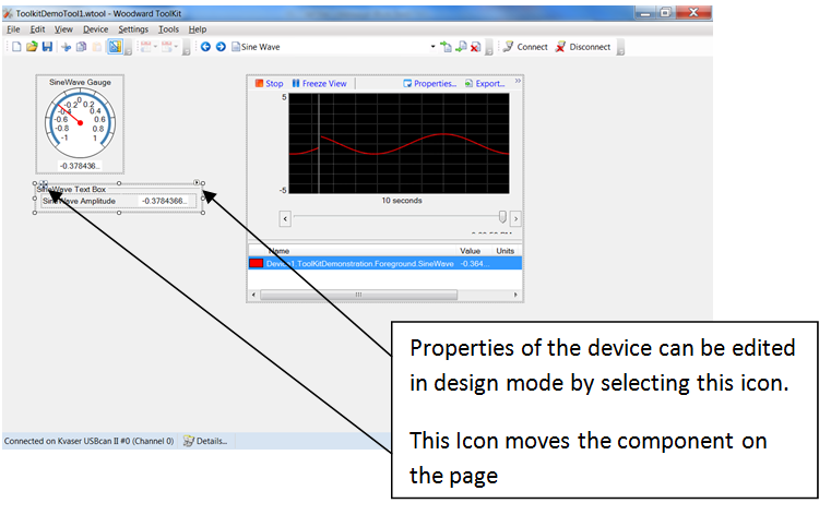
Example 2: Adding a Gauge Component In the Toolkit Demo model, the probe SineWave can be added to a page of the Toolkit tool as a Round Gauge, among other choices. To add SineWave as a gauge, select the SineWave display parameter, then select Round Gauge and double click the page where you want to add the gauge. The SineWave could also be added as different components. It is shown as a Round Gauge, Trend Chart, and Text. Here, the device is connected, so data is being displayed.
Connecting to a Device (ECU)
Click on Connect in order to go on-line with the device (ECU).
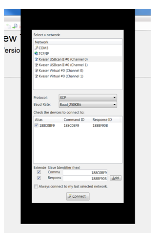
The Window displayed below will open for you to define your network.
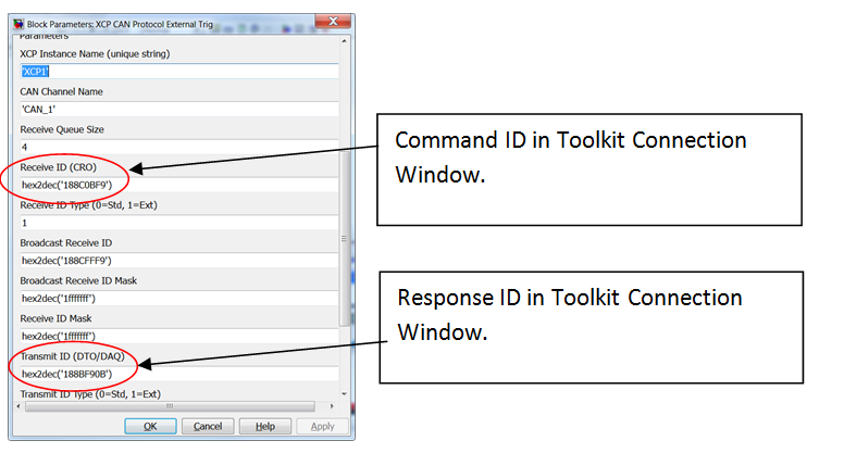
Select your CAN channel, XCP Protocol, and Baud Rate. Then define the addresses for Command and Receive as set in your XCP CAN External Protocol Block in the MotoHawk model.
• Command is the Rx ID as defined in the XCP protocol block.
• Receive is the Tx ID as defined in the XCP protocol block.
Note: Check the checkbox first before entering the Command or Receive ID. The ID is entered in Hex, without 0x, and with no tick marks, quotation marks, etc.
Click Add, then Click Connect
You should then see the values for the tool you have created.
Working with Settings (Calibrations)
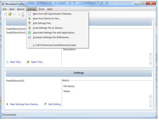
Calibrations, or Settings, can be saved to a file (.wset), loaded onto a device, compared, or exported into an .html file for viewing or editing through the following commands found in the Settings pull-down menu: Toolkit allows for the following actions with Device Settings (Calibrations):
New from SID Specification Defaults
This is supported with MotoHawk when the Toolkit Integration Definition block has "Add default settings to SID" checked.
Save from Device to File
Saves the Calibration Settings from the connected Device to a Settings (.wset file)
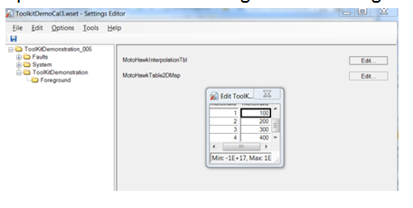
Edit Settings File
Opens the Calibration Settings file for editing. Calibration values can be edited.
Load Settings into Device
Loads the calibration settings onto the device hardware.
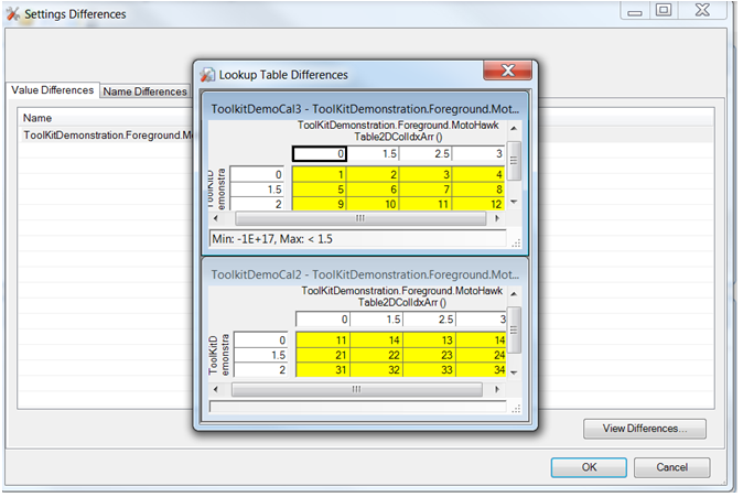
Settings Differences
Compares two calibration settings files. The differences in the settings can be viewed in more detail by selecting the View Differences option.
Associate Settings File with Application
This associates a particular calibration settings file with an application SID file from a build. This can be used to upgrade a settings file (calibrations) from one build to a newer build.
In order to upgrade a calibration settings file from an older build to a newer application build:
1. Save the Settings from Device to File with your desired calibration data from the old build.
2. Program the device (ECU) with the new application
3. Select Associate Settings File with Application and select the SID file from the new build.
4. Load the new Settings File to the Device
Partial Calibrations
A partial calibration settings file can be created, but a partial calibration file cannot be merged into the main application settings file offline. To merge the partial calibration into the main application, first load the main settings into the device (ECU). Then load the partial calibration into the device (ECU). Then, save the settings file from the Device to a File.
Security
Toolkit parameter security is supported in MotoHawk. XCP seed and key security is supported in the XCP slave blockset.
