Reaction Module Blockset
Contents
Reaction Module Setup for Injection Timing
Low impedance injector drivers circuits are based upon switching a MOSFET on and off at frequency to regulate load current. The high frequency switching allows the MOSFET to operate in its more thermally efficient saturated region. The circuits typically monitor load current and switch off when that current exceeds a certain threshold referred to as the “switch-off” current. For the 128-pin ECM for example, the switching is done in the hardware through a chopper circuit. This achieves a fixed peak hold current level.
By comparison, the switching for the SECM112 is accomplished in software using the Reaction Module silicon that is available on the Freescale MPC564x. This gives greater flexibility to the application in setting the current limits at which the circuit will switch off (limits for max peak and max hold current) as well as the fixed amount of time for which the output will be switched off. The Reaction module must be defined, and the Reaction Channels configured for the required timing components and current thresholds to achieve the average current levels required in the application.
The standard PSP blocks (Injector Sequence, Dual PSP, Multiple PSP..) are supported on the SECM112, but configuration of the Reaction Module is Required for Injection on the SECM112. Peak-Hold timing is configured by the Reaction Module, and the peak-hold input port on the sequence blocks is ignored.
The Reaction Module Configuration blocks are located in the Module Configuration library of MotoHawk.
This article will give an overview of the Reaction Channel Blocks. Refer to the Block Help for each block for detailed descriptions of the block usage, limitations, and design considerations.
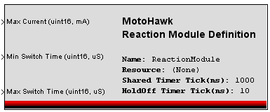
Reaction Module Definition block
This block MUST be placed in the model if injection is required. It defines the global configurations of Freescale Semiconductor’s Reaction Module. If this block is not placed in the model, the following build error will result.
ERROR: A ReactionModule with a ModuleResource of REACT was not found in the application descriptor.
Peak/Hold Controller block and the Reaction Module off Time Definition block
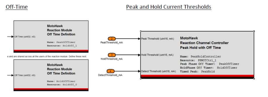
Reaction Channels perform the load current modulation to achieve the desired average current and peak/hold times. Once the Reaction Module is Defined, the Reaction Channel Behaviors must Be configured. The Peak/Hold Controller block selects the control style to be utilized, which is dependent upon the hardware. Possible styles include Peak/Hold with Off Time (PHWOT) and Peak/Hold with Dual Threshold (PHWDT). The controller will allow the Peak Threshold and Hold Threshold values to be used with the modulation to be defined. When the PHWOT control style is in use then the Reaction Module off Time Definition block is needed to defines the fixed amount of time the channel will turn off, once the threshold value is reached.
As an example, one MotoHawk Reaction Channel Contoller Peak Hold with Off Time block is configured, and the Peak Threshold and Hold Threshold are input into the block. Detect Threshold is for fault detection. Also, two Reaction Module Off Time Definition blocks are used in this example. One is controlling the off time for the peak section of the injector output, and the other is controlling the off time for the hold portion. This could be configured differently to fit the specific application needs.
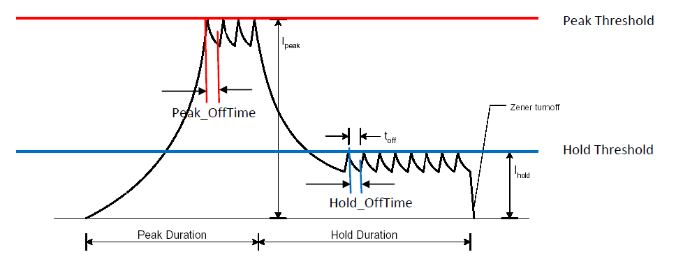
In the waveform below, the injector turns on. Initially it is in the peak portion of the signal. When the Peak Threshold is reached, the output is shut off for the Peak Off Time defined by the Timer block. Similarly, in the Hold portion of the signal, when the Hold Threshold is reached, the hold output shuts off for the Hold Off Time.
Peak/Hold Channel Definition Block
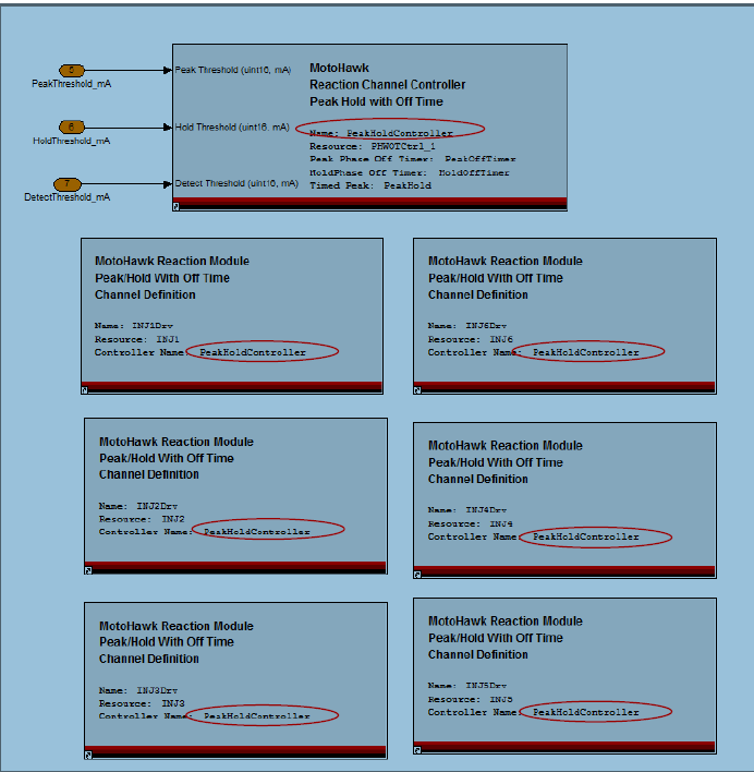
The Reaction Channels are associated to Injector Outputs with the Peak/Hold Channel Definition Block. A controller can be used by more than one channel and so the same controller definition could be used to define how all the injectors on a module operate. Below, as one example, one Reaction Channel Controller resource is defined, and it is associated to 6 injectors.
Timed Peak Hold
The Reaction Channel Controller Peak Hold with Off Time block also has a checkbox for enabling timed peak hold. When this box is checked, the Timed Peak Hold block is used to define the peak time. Peak time set in the Injection blocks (ex. sequence block) is ignored.
Reaction Module Status
The Reaction Module Status block can be used to determine the status of the Reaction Module. The status is described by an enumeration of possible status events.
- 0 = OK
- 1 = Channel Failed to Create
- 2 = Timer Allocation Error occurred since status was last queried
- 3 = Resource Allocation Error occurred since status was last queried
- 4 = Parent Reaction Module Not Created
Channel Failed to Create
A software issue has prevented the Reaction Channel from creating. The Reaction Channel behavior won't operate. The output will be disabled.
Example
An example subsystem showing the Reaction Module blockset is attached. You must be logged into the MCS website to download the example.
Timer Allocation Error The reaction module supports a pool of internal timers that are shared by all of the reaction channels and is of a finite size. A timer may be required during a reaction channel's modulation sequence. For example the PHWOT Reaction Channel behavior utilizes one of these shared timers to implement its peak phase. This error is issued if a channel required a timer, but there was not one available. The reaction channel setup and/or control will need to be modified to prevent this error from occurring. It is brought about by limitations in the Reaction Module silicon.
Resource Allocation Error There were internal software issues that are preventing the reaction channel operating as expected.
Parent Reaction Module Not Created
This channel is dependent upon the Reaction Module creating successfully, which did not occur. The output will be disabled.


