MC33810 Blocks
Some modules use the MC33810 as the driver for their LSO and/or Spark Outputs. MotoHawk contains a blockset of MC33810 configuration and diagnostic blocks that can be used to enable the additional current control and diagnostic capabilities of the MC33810 chip.
Contents
Modules
The MC33810 is used on:
- ECM-S12X-70
- ECM-564x-112 (SECM112)
Diagnostics
The MC33810 has three types of outputs. There are four low side gate drivers and four pre-gate drivers that can function either as ignition IGBT or general purpose MOSFET gate pre-drivers. The fault reporting will depend on which outputs of the MC33810 are being used and whether the pregate drivers are configured for IGBT or MOSFET.
Note: When configured for an IGBT (typically on the ECU spark outputs) the driver diagnostics assume that the load will be an ignition coil. Diagnostics for other loads using the IGBT spark outputs may be impacted.
Output Types
OUT Type: General low side gate drivers
GPGD Type: Pregate driver configured for a MOSFET
IGBT Type: Pregate driver configured for an IGBT
Possible Faults Reported by MotoHawk from the MC33810
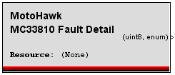
The fault detail is reported by the MotoHawk MC33810 Fault Detail block. This block can report the LAST reported fault of the following faults. The faults that can be reported depend on the type of MC33810 output as well as the MotoHawk block used for the output.
The IO Fault Status block must be used with the IO Fault Detail block because the MC33810 fault detail block reports the last reported fault. It will continue to report a fault after the fault condition has cleared, and is intended only to give additional detail to the application.
(0) No faults observed
(1) Open detected while asserted. Channel is OUT type
(2) Open detected while not-asserted. Channel is OUT type
(3) Short to battery. Channel is OUT type
(4) Temperature limit shutdown. Channel is OUT type.
(5) Open detected. Channel is GPGD type.
(6) Short detected. Channel is GPGD type.
(7) Open secondary detected. Channel is IGBT type.
(8) Max dwell shutdown. Channel is IGBT type.
(9) MAXI current observed. Channel is IGBT type.
(10) Open primary (Nominal current not attained). Channel is IGBT type.
IGBT PreGate Drivers
When these pregate driver (FB0,1,2,or 3) outputs of the MC33810 are configured as IGBT pregate drives, the output expects that they will be used to drive an ignition coil. These would be typical on ECU spark outputs that use the MC33810.
When configured for IGBT type, the following faults can be detected:
(0) No faults observed
(7) Open secondary detected. Channel is IGBT type.
(8) Max dwell shutdown. Channel is IGBT type.
(9) MAXI current observed. Channel is IGBT type.
(10) Open primary (Nominal current not attained). Channel is IGBT type.
MC33810 Spark Control Definition
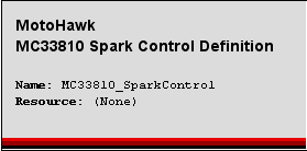
The MC33810 Spark Control Definition block must first be placed in the model to define the global configurations of the MC33810 IC that relate to IGBT control. There will be one block for each MC33810 driver chip.
The fault diagnostics of these outputs are then enabled through the MC33810 Spark Fault Definition block. The Spark Resource (pin) is selected.
NOMI and MAXI Thresholds
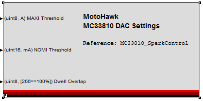
The IGBT pregate drivers use the nominal current value (or NOMI, where I=current) for detection of an open circuit on the ignition coil primary side. The current is also compared to a maximum current value, or MAXI. The MC33810 compares the expected values for NOMI and MAXI across a current sense resistor. If the NOMI level is not reached, an open primary fault (10) is set. Similarly if MAXI is exceeded, MAXI fault is set (9). The NOMI and MAXI values are software configurable to the ranges of 3A to 10.75A for NOMI and 6A to 21A for MAXI using the Motohawk MC33810 Spark DAC Set block, found in Module Configuration blocks.
IGBT type channels use MAXI and NOMI (maximum and nominal current) levels for fault detection. The MAXI and NOMI channels are shared for up to four spark outputs. The diagnostics may not be reliable if the spark signals overlap. This normally is not an issue with the intended use for spark. However, diagnotics would be impacted if driving a different load with a discrete output, for example, as the channels could overlap.
NOMI and MAXI current is only used when the outputs are configured as IGBT pre-gate drivers. These do not apply if pregate driver is configured for a MOSFET (as in an LSO).
NOMI fault detection requires a shutdown event and is not supported if the output is driven by a PWM or Discrete Output block. Open circuit faults on IGBT spark outputs using discrete or PWM block and MC33810 IGBT type outputs will not be reported.
Time to Nominal Current
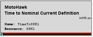
The time to reach the nominal current level can be monitored by the application for control or diagnostics. The Time to Nominal Current Definition block creates a resource that allows the last observed time to nominal load current diagnostic to be read. This block can be used directly to recover the time or the Time to Nominal Current access block used, which references this block.
Open Secondary Fault
In the event that the secondary is open, all of the stored energy in the ignition coil is dissipated by the IGBT. Faults for open secondary can thus be reported by comparing the current on the primary to what is expected given that the secondary is discharging as expected. Again, fault reporting assumes the IGBT output is driving an ignition coil, and incorrect fault reporting can occur when the device is driving something different (ex. a solenoid or pump).
Dwell Time
Dwell time is the duration of time that an ignition coil is allowed to change. The MC33810 starts a timer from when the gate is turned ON. If the dwell time is longer than the Max Dwell setting, a Max Dwell fault can be set. The Max Dwell fault (8) indicates that the channel was shutdown because of an over dwell situation.
Monitoring Spark Duration
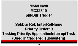
The spark duration can be monitored using the MotoHawk MC33810 Spark Duration Definition and Spark Duration Trigger blocks.
The MC33810 Spark Duration Definition block must be used to select a resource for spark duration measurement. Alternatively the Get MC33810 Spark Duration block can be used. Only a single definition block may exist for each resource, but multiple Get MC33810 Spark Duration blocks may exist. The Spark Duration outport recovers the last observed spark duration for the associated resource in microseconds. A negative value (-1) implies that the MC33810 did not measure a spark duration. Blocks like the MC33810 Spark Control Definition and the MC33810 Spark Fliter Set may need to be configured for the hardware so that it can reliably measure spark duration.
Behavior Limitations
The MC33810 hardware measures the spark duration and exports it to the microcontroller via a single, shared SPKDUR signal. Multiple spark duration definition blocks that target different resources may share the same SPKDUR signal. MotoHawk™ demultiplexes this signal when it is processed, but assumes that the behavior of excitation signal that generates the spark will be generated via PSP. Therefore this behavior will only work with PSP like behaviors including Dual PSP, Multiple PSP and the Spark Sequence blocks.
The SPKDUR signal that the microcontroller interprets to obtain spark duration may also be made available in a raw form via the Input Capture block. Spark duration will be reported if this block is configured to trigger on the rising edge. The Input Capture block may not coexist with the MC33810 Spark Duration block. Use the Input Capture block to construct an application specific spark duration capture mechanism when behaviors besides PSP are to be used.
There is also a MC33810 Spark Duration Trigger block that allows the model to be notified when a spark duration event for the referenced resource is observed.
Note that the spark duration trigger will occur after the excitation (dwelling) event concludes (spark is initiated by the conclusion of the excitation event). Thus it quite likely that a trigger block like the PSP End Trigger will execute before the spark associated with that excitation event has completed. In such a situation the reported spark duration will still be for the previous excitation rather than the excitation that just occurred.
MOSFET (GPGD) Predriver Type
The MC33810 pregate driver can also be configured for MOSFET type. This is determined by the type of output pin used in the model and cannot be changed by the application.
When configured as a GPGD type, the following faults can be reported:
(0) No faults observed
(5) Open detected. Channel is GPGD type.
(6) Short detected. Channel is GPGD type.
Again, the fault state is reported through the IO Fault Status block, and additional detail on the LAST fault observed can be obtained through the MC33810 Fault Detail Block. Open load can be detected when the output is off, and short to battery faults detected when the output is on.
The fault reporting of a GPGD type output is configured by using the Motohawk MC33810 GPGD Fault Configuration Block. This block allows the fault configuration of a GPGD style MC33810 output to be applied.
Retry defines whether an output that has been shutdown because of a detected short circuit will attempt to assert again without first having be turned off by the application.
Short Voltage defines the drain source voltage that triggers a short circuit. Values between 0.5V and 3V are supported by the device.
Short time defines how long the drain source voltage must be above the threshold before a fault is triggered. Values between 30us and 960us are supported by the device.
The default 2.5V MC33810 setting is applied for unconnected or "grounded" inputs.
General Gate Driver Outputs
The following faults can be reported for the general gate driver outputs (OUT channels).
(0) No faults observed
(1) Open detected while asserted.
(2) Open detected while not-asserted.
(3) Short to battery.
(4) Temperature limit shutdown.
The general gate drivers have the capability to detect an open circuit condition even while the drive is asserted. However, there are often requirements on the load that must be met before the diagnostic will operate reliably. The Open Load While Asserted Configuration block allows the application to define whether this diagnostic should be used.
